SERVICE MANUAL TRUNKED PORTABLE RADIO LTR-NET 7243 UHF PORTABLE ™ 7.5VDC 1 and 4 Watts Part No.
7243 LTR-NET™ PORTABLE RADIO SERVICE MANUAL UHF, 430-470 MHz Part No. 242-7243-633 Copyright© 2001 by the E.F. Johnson Company The E.F. Johnson Company, which was founded in 1923, provides wireless communication systems solutions for public safety, government, and commercial customers. The company designs, manufactures, and markets conventional and trunked radio systems, mobile and portable subscriber radios, repeaters, and Project 25 digital radio products.
TABLE OF CONTENTS TABLE OF CONTENTS 1 GENERAL INFORMATION 1.1 1.2 1.3 1.4 1.5 1.6 1.7 1.8 1.9 1.10 1.11 1.12 SCOPE OF MANUAL . . . . . . . . . . . . . . . . . . . . 1-1 TRANSCEIVER DESCRIPTION . . . . . . . . . . .1-1 PART NUMBER BREAKDOWN . . . . . . . . . . .1-1 TRANSCEIVER IDENTIFICATION . . . . . . . .1-1 TRANSCEIVER TUNING . . . . . . . . . . . . . . . . . 1-1 ACCESSORIES . . . . . . . . . . . . . . . . . . . . . . . . . 1-1 FACTORY CUSTOMER SERVICE . . . . . . . .1-2 FACTORY RETURNS . . . . . . .
TABLE OF CONTENTS TABLE OF CONTENTS (CONT’D) 3.7 3.8 3.9 3.10 3.11 TRANSFER MENU . . . . . . . . . . . . . . . . . . . . VIEW MENU . . . . . . . . . . . . . . . . . . . . . . . . . . COMPORTS MENU . . . . . . . . . . . . . . . . . . . . HELP MENU . . . . . . . . . . . . . . . . . . . . . . . . . . ADDITIONAL PROGRAMMING INFORMATION . . . . . . . . . . . . . . . . . . . . . . Program Key . . . . . . . . . . . . . . . . . . . . . . . . . . . Multiple Home Repeaters . . . . . . . . . . . . . . . . .
TABLE OF CONTENTS TABLE OF CONTENTS (CONT’D) 4.9 Limiter (U151A). . . . . . . . . . . . . . . . . . . . . . . . 4-10 Low-Pass Filter (U146A/B) . . . . . . . . . . . . . . . 4-10 SMARTNET DATA PROCESSING . . . . . . .4-10 5 ALIGNMENT PROCEDURE 5.1 GENERAL. . . . . . . . . . . . . . . . . . . . . . . . . . . . . . 5-1 Introduction . . . . . . . . . . . . . . . . . . . . . . . . . . . . 5-1 Special Test Code Required . . . . . . . . . . . . . . . . 5-1 LOADING OPERATING CODE . . . . . . . . . . .
TABLE OF CONTENTS TABLE OF CONTENTS (CONT’D) LIST OF TABLES 1-1 1-2 2-1 3-1 3-2 3-3 3-4 3-5 3-6 4-1 5-1 LIST OF FIGURES 7243 Portable Accessories . . . . . . . . . . . . . . . . . . 1-1 Charger Indicators . . . . . . . . . . . . . . . . . . . . . . . . 1-4 Menu Mode and Option Switch Functions . . . .2-12 Menu and Option Sw. Parameter Descriptions . 3-10 Locality Programming Screen Description . . . . 3-15 System Programming Screen Description . . . . . 3-16 Group Programming Screen Description . . . . .
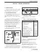
GENERAL INFORMATION SECTION 1 GENERAL INFORMATION 1.1 SCOPE OF MANUAL Model From P.N. This service manual contains operation, programming, alignment, and service information for the E.F. Johnson 7243 LTR-Net™ portable transceiver. 7243 1.2 TRANSCEIVER DESCRIPTION 6 = LTR-Net The 7243 LTR-Net portable transceiver operates in the UHF 430-470 MHz frequency range. Power output is selectable for low (1 watt) and high (4 watt) levels. Accessory 12345 Last Digit of Year Part No.
GENERAL INFORMATION transceiver. The cables from the RPI to computer and transceiver are not included with the RPI and must be ordered separately. Toll-Free: (800) 328-3911 Programming Software E-Mail: customerservice@efjohnson.com You can also e-mail a person directly if you know their first initial/last name (example: jsmith@efjohnson.com).
GENERAL INFORMATION nator (C512, for example) and the model number of the equipment the part is from. repair. Clearly describe the difficulty experienced in the space provided and also note any prior physical damage to the equipment. Include this form in the shipping container with each unit. Your telephone number and contact name are important as there are times when the technicians may have specific questions that need to be answered in order to completely identify and repair a problem.
GENERAL INFORMATION Table 1-2 Charger Indicators 1.12 BATTERY CHARGER INFORMATION 1.12.1 GENERAL Indication The battery pack for the 7243 portable contains six nickel metal hydride (NiMH) batteries connected in series. Nominal battery pack voltage is 7.5 volts and battery capacity is 1450 mAH.
GENERAL INFORMATION 7243 SPECIFICATIONS The following are general specifications intended for use in testing and servicing the transceiver. For current advertised specifications, refer to the 7243 product information sheet available from your E.F. Johnson sales representative. Specifications are subject to change without notice.
OPERATION SECTION 2 OPERATION On-Off/Volume Option Switch 1 • • • • • • • • Antenna Jack Menu mode to select functions Telephone mode for convenient number dialing Three programmable option switches Keypad lock (with and without password) Call indicator Time-out timer Receive-only groups Companding Speaker 2.1.2 LTR-NET FEATURES Microphone The following features are available when an LTR-Net system is selected.
OPERATION Phone Group System Scan List Dial Mode S BUSY Not Used Not Used Low Power Scan Call O L C UID M 8-Character Not Alphanumeric Used Display Conv Ch Busy Low Battery Group Scan List Monitor Priority P2 G Tx UID/Aux Group Transmitter Keyed Keypad Lock Figure 2-2 Display 2.2 CONTROLS AND DISPLAY Option PTT Switch 2 Switch 2.2.1 TOP AND SIDE CONTROLS NOTE: These controls are shown in Figure 2-1. On-Off Volume - Turning this knob clockwise turns power on and sets the volume level.
OPERATION O - Not currently used. L - Indicates that low transmit power is selected (see Section 2.4.8). - Indicates that the scan mode is selected (see Section 2.6.1). - Not currently used. C - Indicates that a call has been received on a group programmed for a call indicator (see Section 2.4.2). Press any key to turn this indication off. Figure 2-3 Front Panel Keys - Indicates that the monitor mode has been enabled by the Monitor option switch (see Section 2.11.2).
OPERATION FCN DIAL - Exits the dial mode without sending the call termination characters. Dial Mode RCL - After recalling a number, scrolls through other numbers programmed in memory. FCN RCL (0-9) - Recalls the number stored in the specified memory location. FCN RCL - Recalls the last number recalled from memory. FCN RCL # - Recalls the last number sent by FCN SND. 4 (PAGE) Standard Mode FCN PAGE - The page function is currently not available.
OPERATION SYS # - Selects the next higher system (see preceding “SYS” key description). GRP # - Selects the next higher group (see preceding “GRP” key description). FCN - Selects the keypad (standard) lock feature. Dial Mode # - Dials the “ # ” digit. FCN - Displays the overflow digits. FCN RCL # - Recalls the last number sent by FCN SND. Dial Mode 8 - Dials the “8” digit. FCN SEND - Automatically transmits the number in the display (after the system has been accessed by briefly pressing the PTT switch).
OPERATION 2.3.4 SYSTEM/GROUP DISPLAY MODE press GRP . As when selecting a system, holding the key down causes the function to repeat, and after the lowest system or group is selected, wraparound occurs. Two system/group display modes can be selected. One is a numeric format and the other is an alpha tag format. To switch between these modes, press FCN STR or select the S/G DISPL menu parameter (see Section 2.5.2). Turning power off does not change the selected mode.
OPERATION locality programmed for one of these modes. The type of operation that is programmed is determined by the type of repeater equipment being accessed. The differences in operation are described in the following information and also noted elsewhere as required. NOTE: This password is not preprogrammed and there is no override procedure. Therefore, if it is forgotten, the transceiver must be reprogrammed to return it to normal operation. 2.3.
OPERATION unique alpha tag and can have a different display number in each bank (see Section 2.4.1). To manually monitor a conventional channel before transmitting to determine if it is being used by someone else, proceed as follows: LTR-Net and LTR systems are programmed with the home repeater number, a collection of groups, and a transmit inhibit block of ID codes (see Section 2.8.4). The home repeater number and group ID code form the address for group calls.
OPERATION Conventional Group Types • If the radio system could not be accessed because of an out-of-range condition or some other reason, the intercept tone sounds (see Section 2.12) and “NO ACCES” is indicated in the display. The PTT switch must then be released and pressed again to make another access attempt. • When responding, busy or no access conditions may also occur the same as when placing a call because the system is re-accessed for each transmission with these calls.
OPERATION system and group of the last call are displayed. Otherwise, the currently selected system/group is displayed. Milwaukee. Up to sixteen banks can be programmed, and each bank is identified by a unique alpha tag. Banks are selected by the BANK menu parameter. In the menu mode, select the “BANK SEL” parameter and then the desired bank as described in Section 2.5.2. If this menu parameter is not available, banks are not selectable.
OPERATION • 2.4.5 ENCRYPTION To enable it on conventional calls, check the “Conventional Enabled” box in the same screen. Encryption is currently not available. The proceed tone normally sounds almost immediately when the PTT switch is pressed. However, with some calls, such as wide area, the user should wait a short time after pressing the PTT switch before speaking. The proceed tone delay of 0-2.5 seconds can be programmed in the Timing Parameters screen.
OPERATION Table 2-1 Menu Mode and Option Switch Functions Function Backlight mode select Bank select Display mode Monitor mode Roaming on-off [3] Scan type select Scan continue on-off Scan list save mode Tone type select Any Keypad Function Menu Item Option Switch BACKLGHT BANK SEL S/G DISPL X ROAMING SCN TYPE SCN CONT SCN SAVE TONES See Description in Section: 2.3.2 2.4.1 2.3.4 2.11.2 2.9.4 2.6.1 2.6.9 2.6.7 2.4.12 [2] NOTES: 1. Functions left blank are not available.
OPERATION exited 2 seconds after a change is made or 8 seconds after no changes are made. and then programming a default condition in the menu mode programming screen. However, if a parameter can be changed by an option switch or menu parameter, the default condition is maintained only until the first time it is changed (cycling power does not reselect the default condition). • 2.6 SYSTEM AND GROUP SCANNING 2.6.1 GENERAL Calls cannot be received or transmitted while the menu mode is selected.
OPERATION detected, registration on that site occurs and only LTRNet systems are again scanned. This operation can provide uninterrupted operation when traveling through areas which have not yet been converted to LTR-Net operation. display mode selected, the system number is replaced by dashes and likewise for the group number when group scanning is occurring.
OPERATION 2.6.6 CONVENTIONAL MODE SCANNING Deleting a system only temporarily deletes the groups associated with that system because when a system is added back into the scan list, the original group scan list is again active. Scan lists can be programmed even when scanning is disabled and while listening to a message. If a system or group is deleted while listening to a message, scanning resumes after the receive delay time expires (if applicable).
OPERATION respond to a call without having to manually change the system/group. To return to the previously selected system/group, it must be manually selected using the SYS and GRP keys or FCN HOME if it was the home system/group. Scan Continue Timer The scan continue timer controls the maximum time that a call is received before scanning resumes. This prevents scanning from being delayed for long periods by lengthy calls. This time can be programmed for 0-60 seconds in 1-second steps.
OPERATION 2.7.4 SENDING THE NUMBER 1. Access the radio system by briefly pressing the PTT switch. Access the radio system by briefly pressing the PTT switch. Then when a dial tone is heard, send the number in the display by pressing FCN SND. The keypad remains active while in a conversation to allow additional numbers to be dialed. Simply press the PTT switch and dial the number. The number in the display does not change when a number is dialed in this manner. 2.
OPERATION 2.7.6 RECALLING NUMBERS FROM MEMORY To receive a standard group call, the group programmed with the ID code being transmitted must be selected or scanned. Calls with a higher priority than the selected group are always received as described in Section 2.8.2. The procedure used to place and receive standard group calls is described in Section 2.3.13.
OPERATION access). The preceding section describes receive priority which controls what calls are received. can be programmed as not interruptible. This has the same affect as programming it with a “1” priority. However, if this was done instead of programming it as not interruptible, calls on that group would interrupt all other lower priority calls which may not be desirable. 2.8.
OPERATION The Directed Group call is received as a standard group call because it is converted to that type by the switch. Therefore, a group programmed with the ID specified by the originating mobile must be selected or scanned or be assigned to a higher priority group. Mobile Disable, and Reassignment are originated by the system operator or a dispatcher. Special LTR-Net calls use the special call group ID codes from 240-254.
OPERATION indicate that the number was accepted by the system. If this beep does not sound, an unauthorized number may have been dialed or a dialing mistake may have been made. If a system resource busy condition exists, the call is placed in a queue by the system (see Section 2.9.3). 3. If placing a unique ID or directed group call, select the auxiliary group in the normal manner using the GRP key. Then select the dial mode by pressing FCN DIAL.
OPERATION message occurs when the PTT switch is released after dialing the digits. Landside-Originate Special Calls Calls can be also be made from any landside telephone to specific mobiles (Unique ID calls) or groups (Directed Group calls). Calls can also be placed to other sites similar to when they are mobile dialed. If resources then become available, ringback is heard and the PTT switch can then be pressed to continue the call.
OPERATION new LTR-Net locality is displayed. The new system is the next higher system with a different locality that could be accessed. For example, if System 3 was selected and System 5 is the next higher system with a different locality number, that becomes the selected system if it can be accessed (wrap-around occurs after the highest system is checked). mobile’s unique ID and the home repeater to be used. The registration information is forwarded to the Call Processor which then knows its location.
OPERATION 2.9.7 HOME CHANNEL ALIASING Capture Percentage - This is the percentage that squelch is tightened on the second and later passes when searching for a new locality (LCL SRCH displayed). This parameter should always be greater than or equal to the Dropout Percentage, and it ensures that registration occurs on a stronger locality. The default level is 46%.
OPERATION make a call, the transceiver enters the telephone operating mode. Repeater Number Programming With Aliasing Since the next lower numbered repeater is monitored when a system with a non-existent home repeater is selected, a numbering scheme should be used that equalizes, as much as possible, the gaps between the active repeaters. This equalizes the loading on the active channels.
OPERATION seconds must elapse between digits or the call is terminated. 5. When the other party answers, press the PTT switch and respond. The PTT switch must be pressed to talk and released to listen the same as with standard group calls. 3. Ringing is then heard by the landside caller while the mobile is being rung. 6. When the call is finished, it should be terminated and the dial mode exited. A call is usually terminated by transmitting either the # or # characters (whichever is programmed).
OPERATION 1. Select a conventional system and group that is not busy. with an LTR-Net or LTR system selected, scanning halts and “NOT CONV” is displayed, but monitoring is not enabled. Refer to Section 2.3.11 for more information on channel monitoring. 2. Press FCN SQL to select the squelch adjust mode. The monitor mode is automatically selected in this mode. The currently selected level is indicated by “SQ xxx” in the display. 2.11.3 TRANSMIT DISABLE ON BUSY 3.
OPERATION data scheme used. The number specified when the code is programmed is actually a seed for a special algorithm used to generate the 23-bit data word. The data is transmitted at a rate of 134.4 bits per second. Therefore, approximately six words are transmitted each second. When the data is decoded, 23-bit samples are taken and then the bits are rotated to determine if a valid code was received.
OPERATION Intercept Tone - This is a siren-like tone (alternating high and low tones) consisting of 700 Hz and 800 Hz tones alternating at approximately a 2 Hz rate. This tone indicates the following no access and error conditions: 2.12.2 LTR-NET SPECIAL CALL TONES • No Access - If this tone sounds 2-3 seconds after pressing the PTT switch and “NO ACESS” is displayed, the data handshake with the repeater could not be completed. The usual cause is an outof-range condition.
OPERATION respond to your transmission. It sounds when you release the PTT switch, and you may partially hear this tone. LCL SRCH - Indicates the transceiver is currently on the second or later pass while searching for a new locality on which to register (see Section 2.9.4). Proceed Tone - This tone consists of two beeps and it tells the landside caller when to enter the five-digit number specifying the mobile being called.
OPERATION 2.13 TEST FUNCTIONS TX DSBL - Indicates that the selected group system is programmed for monitoring only (see Section 2.4.10). With the standard LTR-Net operating code, there is no test mode that can be selected to perform testing. To manually control the transceiver with this code, program temporary conventional channels. When the test operating code is loaded, several test functions are available. Refer to Section 5 for more information.
OPERATION Transfer > Read * Codes or click the toolbar (see Section 3.7). stored and can be read using the programmer (see next section). To return to normal operation, cycle power without the PTT switch pressed or press FCN RCL.* icon in the The screen shown in Figure 2-4 is then displayed which indicates various information about each stored error code. Contact the Customer Service Department as described in Section 1.7 for additional information on the displayed error codes.
PROGRAMMING SECTION 3 PROGRAMMING Remote Programming Interface (RPI) Programming Cable P.N. 597-7200-031 CAUTION Attach the programming cable with the cable end of the connector up as shown. Attempting to attach it the other way may result in damage to the radio. Figure 3-1 Programming Setup 3.1 GENERAL The programming software requires a Windows 32-bit operating system such as Windows 95/98/2000 or NT 4.0 to run. A 16-bit operating system such as Windows 3.1 cannot be used. 3.1.
PROGRAMMING ming software and the same setup used for personality programming. Refer to Sections 3.12 and 5.2 for more information. injecting the transmit audio signal and monitoring receive audio during alignment (see Section 5). Earlier RPI’s, such as Part No. 023-5810-000 or 023-9750000, can be used to perform the standard personality programming described in most of this section. 3.1.
PROGRAMMING 3. Select > Run and then click the Browse button and select the “Setupex.exe” file on the CD. 4. Then click OK and follow the on-screen instructions to install the program.The default directory for the program is C:\Program Files\EFJohnson. If you wish to use some other directory, click Browse and select it or type the name to create a new one. • Program name (LTR-Net Programmer) • Window Minimize, Maximize, and Close buttons 3.3.
PROGRAMMING - Read the programming data from radio (Section 3.7). groups/banks must be programmed (see Section 2.3.12). - Write programming data to a radio (Section 3.7). Saved Info/LTR-Net Locality - Functions like the Flash memory display just described to indicate the amount of space remaining in EEPROM U150 for saved information and LTR-Net localities. - Read error code information stored in radio (Section 2.14) 3.4 PROGRAMMING PROCEDURE - Read version information from the transceiver (Section 3.
PROGRAMMING Title Bar Menu Bar Toolbar - Status/ Function U208 Memory Left Radio Type Being Programmed U150 Memory Left Status Bar - Figure 3-2 Main Window 3. When all parameters in the Radio Parameters Screens are programmed, click the OK button to save all changes or the Cancel button to exit without saving changes. 1. Select Edit > Radio Type and the displayed screen selects the Type, Tier, Frequency Band, and Bandwidth of the programming file (Section 3.6.2). 2.
PROGRAMMING button if deleting a group. To exit without saving the current changes, click only the Done button. and exit, or click the Cancel button to exit without saving any changes. 3.4.5 SYSTEM PROGRAMMING 6. Repeat until the system has been programmed with the desired groups. Then click the Done button to exit. Repeat to program other systems if applicable. Each system is linked to one of the localities.
PROGRAMMING should be used periodically while editing a file to prevent the loss of data if a power failure occurs or program execution is interrupted for some other reason. Files are automatically given the .mbl extension. 1. Connect the computer to the transceiver as described in Section 3.1.6. 2. Download the data to the transceiver by selecting Transfer > Write Setup Params or click in the toolbar. Save As - Same as “Save” except you are prompted to enter a file name.
PROGRAMMING 3.6.2 EDIT RADIO TYPE SCREEN Conventional Enabled - When selected, the proceed tone sounds with conventional calls in addition to LTR-Net/LTR standard calls. The Radio Type screen shown below selects the type, tier, frequency band, and bandwidth parameters of the programming file. This must match the radio being programmed.
PROGRAMMING condition is selected when power is turned on. Refer to Section 2.5.2 for more menu mode information, and to Table 3-1 for brief descriptions of items programmed in the Menu Items screen. Call Delay - Selects the time from 0-7 seconds before scanning resumes after transmitting a message (Section 2.6.9). Scan Continue - Selects the maximum time from 0-60 seconds that a call is monitored before scanning resumes (Section 2.6.9). 3.6.
PROGRAMMING grammed by the user. Numbers of up to 16 digits can be entered, and entering a “@” produces a 1-second pause (each “@” counts as one of the 16 characters). described in Section 2.3.12, a locality is a single repeater site, and it is programmed with the repeaters at that site. Up to approximately 25 LTR-Net or 60 LTR or conventional localities can be programmed. The functions that can be selected by Edit > Localities menu are as follows: Edit > Localities > Create New - Creates a new locality.
PROGRAMMING 3.6.9 EDIT SYSTEM SCREEN The Edit > Systems menu parameter (see Figure 3-3) or equivalent buttons in the toolbar select the screen that sets up and edits systems. As described in Section 2.3.12, a system is programmed with one or more selectable groups and other unique information. Up to 99 systems can be programmed. Groups are added to systems using the group edit function described in the next section. For a system to be selected or scanned, it must be linked to a bank (Section 3.6.11). 3.
PROGRAMMING PROG ERR - Indicates that an error was detected when verifying the data programmed into the transceiver. Read Codes - This menu item or toolbar button reads the error code log stored in the radio and displays it. Refer to Section 2.14 for more information. Read Setup Params - Reads the data contained in a transceiver. This function can be used to check transceiver programming or use the data in one transceiver as the basis for programming another.
PROGRAMMING To disable this feature so that no key is required to read data from the transceiver, do not enter any characters in the Pgm Key box, or if there already is a code in this box, delete all characters. Then program the transceiver with the data file. If the key is lost, contact Customer Service as described in Section 1.7 for information on how this feature can be overridden.
PROGRAMMING microcontroller or a memory device such as an EPROM. For example, the radio software may be updated to correct software bugs or add feature enhancements. This is possible because a reprogrammable Flash memory device is used for program storage. between numbers. For example, a five-repeater system should be numbered 1, 5, 10, 15, and 20. These numbers are programmed in the repeater and also each mobile locality (see Section 3.6.8). If Home Channel Aliasing is used (see Section 2.9.
PROGRAMMING Table 3-2 Locality Programming Screen Description This screen is used to create a new locality or edit a current locality. It is displayed by selecting the Edit > Localities menu (see Section 3.6.8) or clicking one of the buttons in the toolbar. In general, a locality is a repeater site. Parameter Description Locality Name Number This is an eight-character name given to the locality to identify it during programming. It is not displayed by the transceiver.
PROGRAMMING Table 3-2 Locality Programming Screen Description (Continued) Parameter Description Display Selects if repeater frequencies are entered as programming Channel numbers or channel Frequencies. With the Mode UHF band, only channel frequencies can be used, so “Channel” is not selectable. Frequency Programs the frequency of each repeater at the locality (Section 3.11.3). Note that repeater frequencies are entered, not mobile frequencies. Bandwidth Either 12.
PROGRAMMING Table 3-4 Group Programming Screen Description This screen is used to add groups to a system or edit groups already assigned to a system. It is displayed by selecting the Edit > Groups menu or clicking the button in the toolbar (see Section 3.6.10). In the following screens, first select the Group No. to be added or edited from the drop-down list or the list at the bottom.
PROGRAMMING Table 3-4 Group Programming Screen Description (Continued) Conventional Group Programming Screen Parameter Description Group This drop-down list selects the group to be added or edited in the screen. Number Alpha Tag This specifies the eight-character alpha tag that is displayed when the group is selected.
PROGRAMMING Table 3-5 Bank Programming Screen Description This screen is used to create a new bank or edit a current bank. It is displayed by selecting the Edit > Banks menu (see Section 3.6.11) or clicking one of the buttons in the toolbar. In the above screen, select the number of the system to be added or edited in the System Display No. drop-down list and then select the desired parameters. Then make the changes by clicking the Change button (this is an Add button if adding a system).
PROGRAMMING Table 3-5 Bank Programming Screen Description (Continued) Parameter Done Button Cancel Button Default Bank Button Description Click this button when finished editing the bank to save the changes. Click this button to exit the screen without saving any changes to the bank. A default bank can be programmed in the Menu Items screen (Section 3.6.5). Clicking this button assigns the current bank as the default without having to select that screen.
CIRCUIT DESCRIPTION SECTION 4 CIRCUIT DESCRIPTION Regulator U601 on the RF board provides the C5V supply, and regulator U602 provides the T5V and R5V supply. The T5V supply is enabled when the DPTT (delayed PTT) signal goes low, and the R5V supply is enabled when it goes high. The DPTT signal is from pin 85 of the microprocessor, and it also controls R5V supply switch Q204 on the audio/logic board. NOTE: A block diagram of the RF and logic boards is located on page 8-8. 4.
CIRCUIT DESCRIPTION With the receive VCO, Q501 produces the first injection signal in the range of 385-425 MHz which is then amplified by Q502. With the transmit VCO, Q531 produces the transmit frequency in the range of 430-470 MHz) which is then amplified by Q532. the A, N, and reference counters to divide by a certain number. This programming is performed by the microprocessor via the serial data bus which consists of the Clock, Data, and Latch Enable lines (pins 11-14 of U202).
CIRCUIT DESCRIPTION frequency is from the synthesizer, and it is fed through a low pass filter (C520, C521, L506) which attenuates harmonic frequencies present in the injection signal. the C5V input voltage. This converter has a built-in relaxation oscillator and rectifier. The frequency of operation is determined by L201. The built-in rectifier combined with an internal temperature compensated reference provide a stable output voltage with a minimum number of external components.
CIRCUIT DESCRIPTION voltage to the first stage (Vbb Control) is from the power control circuit, and the supply voltage to the last stages (Vcc) is the unswitched battery supply. other inputs are unshifted in phase). This network consists of C410 and ceramic discriminator T401. The detected audio signal is then amplified and fed out of U401 on pin 9. 4.4.2 ANTENNA SWITCH AND LOW-PASS FILTER 4.3.
CIRCUIT DESCRIPTION EEPROM U150, digital potentiometer U147, and LCD driver U501 on the keypad/display board. As forward power increases, the output voltage on pin 7 decreases. U103 then turns off more which decreases the supply voltage applied to Vbb Control of U101. This decreases power to maintain a stable output level. The opposite occurs if forward power decreases. NOTE: A block diagram of the RF and logic boards is located on page 8-8.
CIRCUIT DESCRIPTION Table 4-1 Microprocessor U208 Pin Descriptions (Continued) Pin No.
CIRCUIT DESCRIPTION Table 4-1 Microprocessor U208 Pin Descriptions (Continued) Pin No.
CIRCUIT DESCRIPTION Table 4-1 Microprocessor U208 Pin Descriptions (Continued) Pin No.
CIRCUIT DESCRIPTION Also applied at this point are the DTMF and beep tones. Muting of the DTMF tones is provided by Q201 which is controlled by the pin 34 output of the microprocessor. The beep tones are synthesized by 5V and 0V levels from the microprocessor on pin 65. approximately 150 Hz. Then when a high-frequency Call Guard tone is received, Q103A turns off and the cut-off frequency is approximately 190 Hz.
CIRCUIT DESCRIPTION approximately 300 Hz to attenuate frequencies that could cause interference with the Call Guard signals. U143A is selected. The data output signal on U141C, pin 4 is then applied to pin 24 of U147 which is the input of the digitally controlled potentiometer 1 in that device. The data modulation level is set during alignment and controlled by the logic.
CIRCUIT DESCRIPTION signal from AC floating at half supply to DC levels of 0 and 5 volts that can be detected by the microprocessor. Diodes D141 and D142 charge and discharge C148 and C150 to establish a DC reference on pin 6 of comparator U143B that is the average of the positive and negative going alternations. Q141 turns on in the transmit mode which grounds pin 6 and disables this circuit.
ALIGNMENT PROCEDURE SECTION 5 ALIGNMENT PROCEDURE RPI-Transceiver Cable Part No. 597-7200-031 Remote Programming Interface (RPI) Part No. 023-9800-000 Audio Generator 680-Ohm Speaker Load PC-Compatible Computer CAUTION Make sure that the programming cable is attached to the radio with the cable up as shown. Attempting to attach it the other way may result in serious damage to the radio. 50-ohm Load Signal Generator/ Comm. Monitor Wattmeter Figure 5-1 Alignment Setup Diagram 5.
ALIGNMENT PROCEDURE bility and microphone and speaker audio jacks that are required for alignment. Connect the test setup as shown in Figure 5-1. Refer to Section 3.1 for more information. alignment is complete, the LTR-Net operating software is reloaded. The procedure is described in the following section.
ALIGNMENT PROCEDURE NOTE: The test operating code also provides several transceiver test functions that are described in Section 5.16. 1. Connect the test setup and make sure that the switch on the front of the RPI is set to the Flash programming position (toward the LED so that it indicates amber). 7. When alignment is complete, reload the LTR-Net operating code by clicking the “Set File” button and selecting the “00352xx0.s19” file. Then click the “Program Radio” button.
ALIGNMENT PROCEDURE Figure 5-2 PCTune Tune Radio Screen Display Tune Parameters - Displays the following screen which indicates the settings currently programmed into the transceiver. Display Factory Info Screen 5.3.2 RADIO TUNE SCREEN CAUTION Clicking any of the top six buttons on the Radio Tune screen in Figure 5-2 selects that test and immediately keys the transmitter. Therefore, make sure that no test equipment is connected to the antenna jack that could be damaged.
ALIGNMENT PROCEDURE adapter may be required to connect test equipment to this jack. An SMA male to BNC female adapter is available by ordering Part No. 515-3102-060. ments that are performed are shown on the eight buttons on the left side. To perform just one adjustment or perform the adjustments individually, click the applicable button for that adjustment. Alternatively, to have the program automatically step through all adjustments, click the “Tune Entire Radio” button on the top.
ALIGNMENT PROCEDURE 5.7 LOW RF POWER ADJUST connected to the accessory jack. Make sure that the switch on the RPI is away from the LED so that it indicates green. 1. If manually selecting each test, click the “Low Power” button in the screen shown in Figure 5-2. Otherwise, this function is selected automatically after completing the preceding High Power adjustment. The following sections describe the adjustments that are made to align the transceiver. 2. Set the low power output for 1.
ALIGNMENT PROCEDURE ceiver must be opened as described in the next section to access the adjustment point. 2. Inject a 1 kHz signal at the level indicated on the screen into the Mic Audio jack of the RPI (see Section 5.4.1). 5. Set the signal generator for the output signal displayed on the screen and slowly adjust squelch potentiometer VR401 (see Figure 5-3) until the receiver just squelches (audio mutes). 3.
ALIGNMENT PROCEDURE PERFORMANCE TESTS 5.14 RECEIVER PERFORMANCE TESTS 2. Decrease the signal generator output to obtain a 12 dB reading on the SINAD meter. The signal generator output should be 0.35 µV maximum. 5.14.1 PRELIMINARY SETUP With the standard LTR-Net operating code, the transceiver does not have a special test mode that can be selected to perform testing. Therefore, program temporary conventional channels or use the functions available with the test code to perform this function. 3.
ALIGNMENT PROCEDURE 5.15 TRANSMITTER PERFORMANCE TESTS 5.15.3 TRANSMIT MODULATION 5.15.1 POWER OUTPUT 1. Select a channel not programmed for Call Guard (CTCSS/DCS) squelch and monitor the transmit signal with a communication monitor. Speak into the microphone with a normal voice and modulation should be approximately 3.4 kHz (wideband) or 1.4 kHz (narrow band). Refer to Section 5.14.1 for information on test channels. Proceed as follows: 1.
ALIGNMENT PROCEDURE 5.16 TEST CODE FUNCTIONS most six characters of the display (the right digit indicates the group number as described in the next section). The last selected channel is saved at power down. The test channels are listed in Table 5-1. 5.16.1 GENERAL When the special test operating code has been loaded as described in Section 5.2.3, various test channels and test functions can be selected.
ALIGNMENT PROCEDURE 5.16.5 PARAMETER EDIT MODES Selecting Parameters General The parameters that can be selected and the key sequence used to select each are as follows: Some levels set during alignment can be manually controlled by selecting the Parameter Edit mode. This mode is selected and controlled by the following keys: FCN 5 (Receive RF Bandpass Filter) - Changing the number changes the center frequency.
LTR-NET OVERVIEW SECTION 6 LTR-NET OVERVIEW Locality 1 Locality 2 Locality 3 Viking® VX Repeaters Viking® VX Repeaters Viking® VX Repeaters Data Bus Data Bus Subscriber Units Data Bus Subscriber Units Subscriber Units Voice and Data Link System and Subscriber Manager Voice and Data Link Voice and Data Link 3000-Series Switch 3000-Series Switch Public Switched Telephone Network (PSTN) Call Processor Call Processor Ethernet Link Ethernet Link Ethernet Link Figure 6-1 LTR-Net System Dia
LTR-NET OVERVIEW • System Control Current LTR subscriber units can remain in service and LTR-Net subscriber units added gradually. This makes upgrading to LTR-Net very convenient and less costly. • When new channels are added to a locality, subscriber units can be updated with those channels over the air. This eliminates the need to bring them back in for reprogramming. • Over-the-air subscriber unit programming allows the ID codes of up to 99 systems and 99 groups to be changed.
LTR-NET OVERVIEW • Typical access time for group calls is the same as with LTR operation. information for all subscriber units on that locality. Refer to Section 6.6 for more information. • Priority access, automatic emergency calls, status messaging, and system security keys are not available. System, Radio - This refers to the radio equipment and other infrastructure that is accessed when a call is placed. System, Selectable - A subscriber unit has selectable systems and groups.
LTR-NET OVERVIEW A “locality” refers to repeaters at the same location that are interconnected by a common high-speed data bus. Up to 20 repeaters can be interconnected, so a locality can include up to 20 repeaters. Although more than 20 repeaters could be co-located, they would be considered separate localities because they are not interconnected by the same data bus. A single data bus can be up to 500 feet long.
LTR-NET OVERVIEW 6.2.5 CALL PROCESSOR information can then be exported and used by billing software to generate customer billing. The Call Processor is a Windows NT-based personal computer running switch management software. The Call Processor serves as an interface between the switch and the System and Subscriber Manager (see next section). It contains the database used to process calls on the switch and also logs call information from the switch.
LTR-NET OVERVIEW • • 6.5.3 TELEPHONE CALLS The call is routed to a specified locality only if a call on the home/group has been recently detected. This results in more efficient use of system resources. Telephone calls allow calls to be placed over the public switched telephone network. After the system is accessed, a dial tone sounds and the telephone number being called is entered using the DTMF keypad.
LTR-NET OVERVIEW repeater, it continues to monitor that repeater. If a message is detected that has its home repeater as the “channel-in-use” or “free” repeater, the subscriber unit then returns to monitoring its home repeater. voice on any repeater because the data occupies the subaudible frequencies below the voice band. 6.6.2 HOME REPEATERS A roaming subscriber unit also monitors the status repeater in this manner when the home repeater signal drops below the threshold level.
LTR-NET OVERVIEW edge message, and this will be indicated on the system manager’s screen. Uses of unique ID codes include registering and de-registering on a locality, unit identification, airtime billing, and unique ID calls (see “Unique ID Calls” in Section 6.5.2). A call can also be made to individual subscriber units using a group call if the group is assigned to only one subscriber unit. 6.7.
LTR-NET OVERVIEW When a new locality is located, the subscriber unit registers on the locality by sending messages indicating its unique ID code and the home channel it will monitor. The system then knows the location of that subscriber unit and will automatically route unique ID calls to the new locality. system from wasting resources trying to reach out-ofservice units. Power is automatically held on until this message is sent. De-registration is not available with 8170 portable transceivers.
PARTS LIST SECTION 7 PARTS LIST KEYPAD/DISPLAY BOARD ASSEMBLY Ref No Description Part No.
PARTS LIST KEYPAD/DISPLAY BOARD ASSEMBLY Ref No Description RF BOARD ASSEMBLY Part No.
PARTS LIST RF BOARD ASSEMBLY (CONT’D) Ref No C136 C137 C138 C140 C141 C142 C143 C144 C145 C201 C202 C203 C206 C207 C208 C210 C211 C214 C215 C216 C218 C219 C220 C221 C222 C223 C224 C225 C227 C301 C302 C303 C304 C305 C306 C307 C308 C312 C313 C314 C315 C316 C317 C318 C320 C321 Description Part No.
PARTS LIST RF BOARD ASSEMBLY (CONT’D) Ref No C506 C507 C508 C510 C511 C512 C513 C514 C515 C516 C517 C518 C520 C521 C529 C530 C531 C532 C533 C534 C535 C536 C537 C538 C539 C540 C541 C544 C545 C546 C547 C548 C550 C551 C601 C602 C603 C604 C605 C606 C607 C608 C610 C611 C612 Description Part No.
PARTS LIST RF BOARD ASSEMBLY (CONT’D) Ref No Description Part No.
PARTS LIST RF BOARD ASSEMBLY (CONT’D) Ref No Description Part No.
PARTS LIST LOGIC BOARD ASSEMBLY Ref No Description Part No.
PARTS LIST LOGIC BOARD ASSEMBLY (CONT’D) Ref No Description Part No.
PARTS LIST LOGIC BOARD ASSEMBLY (CONT’D) Ref No R112 R113 R114 R115 R116 R117 R118 R119 R120 R121 R122 R123 R124 R125 R126 R127 R128 R129 R141 R142 R143 R144 R145 R146 R147 R148 R149 R150 R151 R152 R153 R154 R155 R156 R157 R158 R160 R161 R162 R163 R164 R165 R167 R168 R170 Description CR 1/16W 394JV resistor CR 1/16W 124JV resistor CR 1/16W 273JV resistor CR 1/16W 564JV resistor CR 1/16W 154JV resistor CR 1/16W 562JV resistor CR 1/16W 103JV resistor CR 1/16W 154JV resistor CR 1/16W 223JV resistor CR 1/16W
PARTS LIST LOGIC BOARD ASSEMBLY (CONT’D) Ref No R233 R234 R235 R236 R237 R238 R240 R241 R242 R243 R244 R251 R252 R255 R256 R257 R261 R262 R263 R265 R266 R267 R280 R301 R302 R303 R304 R305 R306 U101 U102 Description CR 1/16W 104JV resistor CR 1/16W 472JV resistor CR 1/16W 471JV resistor CR 1/16W 105JV resistor CR 1/16W 684JV resistor CR 1/16W 334JV resistor CR 1/16W 104JV resistor CR 1/16W 104JV resistor CR 1/16W 104JV resistor CR 1/16W 000JV resistor CR 1/16W 000JV resistor CR 1/16W 471JV resistor CR 1/1
PARTS LIST MECHANICAL PARTS Item No. From Pg 6-12 Desig. / Locator 1 A004* 2 3 4 5 6 7 8 9 10 11 12 13 14 15 16 17 18 19 20 21 22 23 24 25 26 27 28 29 30 31 32 33 34 35 36 37 38 39 40 41 42 43 * Service Parts Assembly Description Part No.
PARTS LIST EXPLODED VIEW 7-12 November 2001 Part No.
SECTION 8 SCHEMATIC DIAGRAMS AND COMPONENT LAYOUTS RF BOARD J101 AUDIO/LOGIC BOARD J1 Battery In Modulation In 1 2 Battery Out Modulation Out Battery In Sw Narrow/Wide In 3 4 Battery Out Narrow/Wide Out J2 J801 KEYPAD/DISPLAY BOARD Sw Battery In Gnd 1 2 Sw Battery Out Gnd Display Strobe Out Serial Clk Out 3 4 Display Strobe In Serial Clock In NC Power Control In 5 6 TMUT Tx Power Out Display Enable Out L5V Out 5 6 Display Enable In L5V In RSSI Out BPF Shift In 7 8 RSSI In BPF Shi
BANDPASS FILTER C304 3pF C302 7pF C305 3pF C303 18pF R5V R305 3.3k R304 8.2k C306 18pF C308 3pF C320 12pF C314 3pF S301 18nH L304 18nH C318 3pF R303 Q301 680 AT-41533 C307 5pF BANDPASS FILTER C322 C325 5pF 4pF C321 9pF C323 5pF R301 100k C330 2pF R302 100k D303 C326 6pF L301 L308 22nH R307 100k 45.3 MHz CRYSTAL FILTERS C337 5pF L307 18nH XFL401 1 XFL402 3 1 C401 16pF 2 R401 180k R400 330 C420 1000pF C418 0.01 R402 1.5k C406 22pF Q401 2SC3356 3 16 C403 5pF C407 0.
6 5 C 16 1 E E B 3 8 9 2 C 1 E 4 2 1 2 3 4 C E B E C B 19 E E B 10 B E C 11 20 C C C E 1 RT401 B C E B B C C E B 20 E 1 E C B C 11-23-00 Antenna Jack RF BOARD BOTTOM VIEW RF BOARD TOP VIEW 8-3 November 2001 Part No.
MICROCONTROLLER Rx AUDIO GATE 20 NPSPAC 10 Wide/Narrow 19 Q101 R101 UMT3904 10k R104 10k Q102 UMT3904 R102 56k 300-3000 Hz BANDPASS FILTER R112 390k C101 0.01 R107 0 Rx Audio In R108 47k C105 0.039 R113 120k R114 27k C108 1 8 6 7 4 R111 100k Rx Audio Out C106 0.01 5 + R5V R118 10k C110 1 R120 22k 6 Out 1 Comp In +5S 16 R119 150k Vdd Comp Out 13 NC 5 Comp Cap +5S C117 0.1 C114 0.01 R121 100k 2 1 C115 0.
C 1 B E J106 E B C J103 1 61 J104 91 1 2 E B 15 16 C B C E B 31 120 19 1 1 20 C E B E C 30 11 20 10 1 1 1 1 C 1 1 E B 10-5-00 10-5-00 LOGIC BOARD TOP VIEW LOGIC BOARD BOTTOM VIEW 8-5 November 2001 Part No.
KEYPAD Sw Batt J801 Sw Batt Out 21 22 23 24 25 26 27 28 29 30 S11 "0" S8 "8" S5 "5" C110 100pF S2 "2" R413 100k KEYR2 KEYR3 S12 "#" S9 "9" S6 "6" KEYS3 NC R401 47k AMUT Keypad Interrupt R414 100k R402 47k S13 "FCN" (F1) S14 "SYS" (F2) R440 S15 "GRP" (F3) Open R1 R2 MIC KEYS4 R3 NC MSO R415 100k PTT/Flash GND BATT L5V S4 R403 47k Q401 DTA123 Q402 DTA123 Q403 DTA123 R404 47k Sw Batt R104 47k R102 47k R409 100k KINT R416 47k INTA + 8 INTA 5 INTB 6 INTB + External Speake
U5 Mic 22 1 D901 D902 EH1 1 10-5-00 48 23 44 S13 J802 S1 E B C C GRP D303 D304 E B S15 SYS FCN 1 20 S14 S2 3 2 1 D306 Top Panel Option Sw S3 D305 - S4 S5 S6 4 5 6 4 S9 6 8 10 2 D307 D308 B C E B C E C C C S7 B E B E B E B E S8 C C C C 7 C B E B E B E B E D310 8 D309 9 S10 S11 S12 * 0 # + To Accessory Connector 1 3 S902 Upper Opt Sw S901 PTT Sw S903 Lower Opt Sw To Speaker 5 7 9 C C B E B E 16 30 J801 1 15 To J802 (Keypad/Di
AUDIO/LOGIC BOARD RECEIVE AUDIO PROCESSING 300-3000 Hz Audio Bandpass Filter Expander Gate U101A, U101B U202 U204B DTMF U201 MICROCOMPUTER 36 PE2 U208 65 P26 Tones RF BOARD 108 96 RF Amp Two-Pole BP Filter 45.
Part Number 001-7240-001NR 11-01hph Printed in U.S.A.