
Service manual

OPERATION
2-2
November 2001
Part No. 001-7240-001
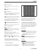
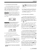
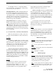
Figure 2-2 Display
BUSY
G
S
UID
Tx
P
2
C
L
O
M
System
Scan List
Phone
Group
Group Scan
List
Scan
Call
8-Character
Alphanumeric
MonitorNot Used
Keypad
Dial
Mode
Low
Power
Not
Used
Priority
Transmitter
Keyed
Lock
UID/Aux
Group
Low
Battery
Not
Used
Conv Ch
Busy
Display
2.2 CONTROLS AND DISPLAY
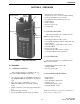
2.2.1 TOP AND SIDE CONTROLS
NOTE: These controls are shown in Figure 2-1.
On-Off Volume - Turning this knob clockwise turns
power on and sets the volume level. Turning it coun-
terclockwise to the detent turns power off. Power is on
when information appears in the display. Refer to
Section 2.3.3 for more information on setting volume.
Option Switch 1 - This switch can be programmed to
control a specific function (see Section 2.5.1).
Antenna Jack - Connection point for the antenna.
Accessory Connector - When the protective cover is
removed, this connector can be used to access PTT,
speaker, and microphone lines for transceiver service
and testing. It is also the connection point for the
computer when programming the transceiver.
Battery Release Button (Not shown) - This button is
located on the bottom end of the transceiver, and it is
pressed to release the battery so that it can slide down-
ward and be removed from the radio.
NOTE: Turn off transceiver power before removing
the battery. This ensures that current settings are prop-
erly saved and the de-registration message is sent.
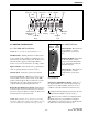
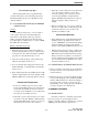
2.2.2 SIDE CONTROLS
Option Switch 2 - This switch can
be programmed to control a
specific function (see Section
2.5.1).
PTT (Push-To-Talk) - This switch
keys the transmitter so that a
message can be transmitted. The
“
Tx” icon is displayed when the
transmitter is keyed.
Option Switch 3 - This switch can
be programmed to control a
specific function (see Section
2.5.1).
2.2.3 DISPLAY
8-Character Alphanumeric Display - This area of
the display indicates the selected system and group
(Section 2.3.4), dialed number (Section 2.7), error
conditions, and other information (Section 2.12.4).
- Indicates that the displayed system is in the scan
list and scanned normally (see Section 2.6.7).
- The base portion of this icon is displayed when
the displayed group is programmed for telephone
calls, and the top portion (receiver) is displayed when
the dial mode is selected (see Section 2.7).
S
Option
Switch 2
PTT
Switc
h
Option
Switch 3