
Service manual


4-1
March 2000
Part No. 001-3139-502
RECEIVER MULTIPLEXER MODULE (RMM)
SECTION 4 RECEIVER MULTIPLEXER MODULE (RMM)
4.1 GENERAL
The Receive Multiplexer Module (RMM), in the
Remote Site, receives RSSI data from multiple RDMs
and multiplexes the information onto a single line to
be transmitted to a CDM at the Local Site.
The RMM is installed in a drawer located at each
of the Remote Receiver Sites (see Figure 1-4). The
RMM is powered from +12-16V DC (average +13.8V
DC) and operates in the temperature range of -30°C to
+ 60°C (-22°F to +140°F) with 10% to 90% humidity.
Each RMM is capable of handling 10-RDMs,
with 3-RMMs required per 30 channel Site. With
3-RMMs per Site (maximum) and 32 voted receiver
Sites, the maximum number of RMMs is 3 x 32 = 96
.
4.2 RECEIVE CALL ORDER OR RSSI DATA
The RMM receives the RSSI information from
the Receiver Decoder Module (RDM) on the RS-232
input. The RS-232 input is set to 1200 baud (refer to
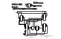
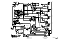
Figure 4-1
).
Figure 4-1 RMM BLOCK DIAGRAM
4.3 DATA PACKET
The RMM creates a Data Packet to be sent to the
Central De-Multiplexer Module (CDM) at the Local
Site. The RMM multiplexes the information received
from a maximum of 10-RDMs.
The RSSI packet consists of 8-bits of information
for each of the 10 possible channels. The first 4-bits
define the channel and second 4-bits indicate the RSSI
level.
The RSSI operation communicates at 1200 baud
to the CDM via an FSK audio line.
Table 4-1 RMM RSSI INFORMATION
Hex Value DESCRIPTION
7
6
5
4
Strongest RSSI signal level
Weakest RSSI signal level a call will be
started at
3
2*
1
0*
Weakest RSSI level before a call will be
dropped.
Time-Out no update received
No Data received from RDM (generated
by RMM only)
Turn-off Code received from mobile
* Idle state.