
Operator's Manual


ALIGNMENT PROCEDURE
5-3
September 2001
Part No. 001-5100-001
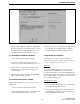
Figure 5-2 Tuning Software Screen (800 MHz Models)
4. The preceding 3 kHz and 1 kHz tone adjustments
are then repeated on several other frequencies across
the band. After the last adjustment is made, the
transmitter unkeys and the settings are stored.
5.4 TRANSMIT POWER ADJUSTMENT
Set transmitter power output as follows:
1. Connect a wattmeter and 50-ohm load to the
antenna jack. Click OK with “TX Power” selected.
2. Follow on-screen instructions to adjust for the
displayed power output at various frequencies
across the band.
3. When the last setting is complete, the transmitter
unkeys and the settings are stored.
5.5 RECEIVE SENSITIVITY TUNING
NOTE: This adjustment is not performed with 800
MHz models.
The receiver front end is tuned as follows:
1. Connect an RF signal generator to the antenna jack.
Click OK with “RX Sensitivity” selected.
2. Inject the frequencies and signal levels indicated on
the computer screen. When tuning is complete, a
message is displayed and the settings are saved.
5.6 SQUELCH ADJUSTMENT
NOTE: With some early models, this adjustment
cannot be made using the PCTune software so an error
message is displayed when it is selected.
Test Setup
This adjustment requires access to the receive
audio signal so that SINAD can be measured. It is
recommended that this be done using the RIB (Radio
Interface Box). This box allows the receive audio signal
to be monitored while the computer is connected to the
accessory/programming jack.
Adjustment Procedure
1. Connect an RF signal generator to the antenna jack.
Click OK with “Squelch” selected.
2. Set the signal generator for the indicated frequency
and modulation. Adjust the generator output level
for 12 dB SINAD and click OK.