
User's Manual


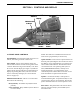
Table Of Contents
- SAFETY INFORMATION
- TABLE OF CONTENTS
- SECTION 1 GENERAL
- SECTION 2 CONTROLS AND DISPLAY
- SECTION 3 GENERAL OPERATION
- SECTION 4 RADIOWIDE FEATURES
- SECTION 5 CONVENTIONAL FEATURES
- 5.1 Introduction
- 5.2 Monitoring Before Transmitting
- 5.3 Monitor Mode
- 5.4 Busy Channel Lockout
- 5.5 Call Guard Squelch
- 5.6 Penalty Timer
- 5.7 Conversation Timer
- 5.8 Repeater Talk-Around
- 5.9 Displaying Transmit/Receive Frequency
- 5.10 Emergency Alarm and Call
- 5.11 Conventional Mode Scanning
- 5.12 Standard Conventional Calls
- 5.13 DTMF/ANI Signaling
- 5.14 Single Tone Encoder
- 5.15 Project 25 Mode Features
- 5.16 Keypad Programming
- SECTION 6 SMARTNET/SMARTZONE/P25 TRUNKED FEATURES
- 6.1 Introduction
- 6.2 Analog and Digital Operation
- 6.3 Viewing Unit ID
- 6.4 Standard Group Calls
- 6.5 Private (Unit-To-Unit) Calls
- 6.6 Telephone Calls
- 6.7 Call Alert
- 6.8 Messaging
- 6.9 Sending Status Conditions
- 6.10 Emergency Alarm and Call
- 6.11 Failsoft Operation
- 6.12 SMARTNET/SmartZone/P25 Trunked Scanning Features
- 6.13 Dynamic Regrouping
- 6.14 SmartZone and P25 Trunking Unique Features
- SECTION 7 MISCELLANEOUS
- SECTION 8 DETERMINING AVAILABLE OPTIONS
- SECTION 9 5300 MOBILE FIRMWARE VERSIONS
- SECTION 10 PASSWORD DESCRIPTION
- SECTION 11 SECURE COMMUNICATION (ENCRYPTION)
- INDEX

10
CONTROLS AND DISPLAY
SECTION 2 CONTROLS AND DISPLAY
Figure 2-1 Front Panel Controls
Six Option
Switches
Display
Microphone
PTT Switch
Speaker
Select
Switch
On-Off/
Volume
Multi-function
Indicator
Six Option
Switches
Display
Microphone
PTT Switch
Speaker
Select
Switch
On-Off/
Volume
Multi-function
Indicator
2.1 FRONT PANEL CONTROLS
On-Off/Volume - Pressing this control turns power on
and off, and rotating it sets the volume level.
Select Switch - Selects zones/channels and is also
used for other functions such as selecting names from
a call list. When selecting zones/channels, a bar above
the zone or channel display (see Figure 2-3) indicates
which is being changed. This bar is switched between
displays by pressing this switch, and zone and chan-
nels are selected by rotating it (see “Zone/Channel
Select” on page 15).
Multi-function Indicator - This is a two-color LED
that indicates the following:
Red (constant) - Transmitter keyed (PTT switch
pressed).
Green (constant) - Busy condition (carrier detected
in receive mode).
NOTE: This indicator is disabled when the Surveil-
lance mode is programmed (see Section 4.9).
Option Switches - Each of the six options switches on
the front panel (including the one located to the left of
the display) can be programmed by your system oper-
ator to control some function. The switch functions
can be different for each operating mode (conven-
tional, SMARTNET/SmartZone, and Project 25
Trunked). Therefore, up to 18 functions can be
controlled by these switches. Refer to Section 4.1 for
more information on option switch functions.
Speaker - An internal 16-ohm, 5-watt speaker is
located behind the grille. An optional 4-ohm, 12-watt
external speaker may be used if desired. The internal
speaker is disabled when an external speaker is used.
PTT Switch - This push-button switch on the micro-
phone is pressed to talk (key the transmitter) and
released to listen.