
User's Manual


CONTROLS AND DISPLAY
8
Revised August 2002
Part No. 001-5300-007CD-NR
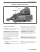
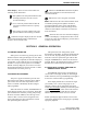
Figure 2-2 Rear Panel Jacks
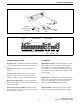
Figure 2-3 Front Panel Display
Remote Control
Unit Jack
Accessory
Jack
Antenna
Jack
DC Power
Jack
Optional
Telephone/Special
Call Channel
Encryption
10-Character Alphanumeric Display
Zone
No.
Status
Display
Chnl
No.
Scan Edit
Mode
2.2 REAR PANEL JACKS
DC Power Jack - Connection point for the nominal 12-
volt, negative ground power source (see Figure 2-2).
Antenna Jack - Type N jack for connecting the
antenna.
Accessory Jack - Black connector for connecting
optional accessories such as an external speaker
(4-ohm, 12-watt), horn alert, and ignition sense line.
Remote Control Unit Jack - Connection point for a
remote control unit if used. This cable is optional with
front-mount models.
Siren Control Jack (Not Shown) - Yellow/orange
connector similar to the accessory jack for connecting
the optional siren controller.
2.3 DISPLAY
Alphanumeric Display - This 10-character area of the
display indicates the alias (unique identification) for
the selected zone or channel, depending on which
select mode is active. It may also indicate such things
as the channel frequency, ID numbers, and status and
error messages.
Zone Number - Indicates the currently selected zone
from 1 up to 16. A zone is a collection of channels that
can be any combination of the conventional, P25
Trunked, and SMARTNET/SmartZone types.
Channel Number - Indicates the currently selected
channel (conventional) or talk group (other modes).