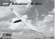
ARF ALMOST-READY-TO-FLY Allusive ™ 2.
NOTICE SAFETY WARNINGS AND PRECAUTIONS SAFE OPERATING RECOMMENDATIONS All instructions, warranties and other collateral documents are subject to change at the sole discretion of Horizon Hobby, Inc. For up-to-date product literature, visit horizonhobby. com and click on the support tab for this product. Read and follow all instructions and safety precautions before use. Improper use can result in fire, serious injury and damage to property.
HINWEIS Alle Anweisungen, Garantien und anderen zugehörigen Dokumente können im eigenen Ermessen von Horizon Hobby, Inc. jederzeit geändert werden. Die aktuelle Produktliteratur finden Sie auf horizonhobby.com unter der Registerkarte „Support“ für das betreffende Produkt.
REMARQUE La totalité des instructions, garanties et autres documents est sujette à modification à la seule discrétion d’Horizon Hobby, Inc. Pour obtenir la documentation à jour, rendez-vous sur le site horizonhobby.com et cliquez sur l’onglet de support de ce produit.
AVVISO Tutte le istruzioni, le garanzie e gli altri documenti pertinenti sono soggetti a cambiamenti a totale discrezione di Horizon Hobby, Inc. Per una documentazione aggiornata sul prodotto, visitare il sito www.horizonhobby.com e fare clic sulla sezione Support per questo prodotto.
SPECIFICATIONS•SPEZIFIKATIONEN• SPÉCIFICATIONS•SPECIFICHE LARGE PARTS LAYOUT•BAUTEILE (OHNE KLEINTEILE)•GRANDES PIÈCES•SCHEMA DEI COMPONENTI GRANDI 87.5 in (2.20m) 4 4 546 sq in (35.2 dm2) 2 3 1 43.0 in (1.10m) 48.0 oz (1.
REPLACEMENT PARTS•ERSATZTEILE•PIÈCES DE RECHANGE•RICAMBI Part English Deutsch Français Italiano 1. EFL492501 Right Wing Panel Tragfläche rechts Aile droite Semiala destra 2. EFL492502 Left Wing Panel Tragfläche links Aile gauche Semiala sinistra 3. EFL492503 Fuselage Rumpf Fuselage Fusoliera 4. EFL492504 Stabilizer Set Leitwerksset Stabilisateurs Set stabilizzatore 5. EFL492505 Hardware Pack Kleinteilepaket Sachet d’accessoires Viti e accessori 6.
REQUIRED TOOLS•BENÖTIGTES WERKZEUG•OUTILS REQUIS•ATTREZZI NECESSARI English Deutsch Français Italiano Box wrench: 12mm Ringschlüssel: 12mm Clé plate fermée 12mm Chiave a tubo: 12mm Clear tape Transparentes Klebeband Adhésif transparent Nastro trasparente Drill bit: 1/16-inch, 5/64-inch Bohrer: 1,5 mm, 2mm Foret : 1,5 mm, 2mm Punte per trapano: 1,5 mm, 2mm Electrical tape-white Isolierband weiss Ruban adhésif d’électricien blanc Nastro elettrico bianco Felt-tipped pen Faserstift Feutre
BEFORE STARTING ASSEMBLY VOR DEM ZUSAMMENBAU • Remove parts from bag. • Entnehmen Sie zur Überprüfung jedes Teil der Verpackung. • Inspect fuselage, wing panels, rudder and stabilizer for damage. • If you find damaged or missing parts, contact your place of purchase. If you find any wrinkles in the covering, use a heat gun (HAN100) and covering glove (HAN150) or covering iron (HAN101) with a sealing iron sock (HAN141) to remove them.
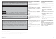
CONTROL HORN INSTALLATION•EINBAU DER RUDERHÖRNER•INSTALLATION DES GUIGNOLS•INSTALLAZIONE DELLE SQUADRETTE 1 2 3 4 LL RR 15 Aileron Control Horns• Querruderhörner•Guignol des ailerons•Squadrette per alettoni LL RR Ruddervator Control Horns• V-Leitwerkshörner•Guignols de stabilisateurs•Squadrette per coda a V Use sandpaper to lightly sand the bottom of the control horn where it fits into the control surface.
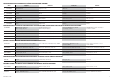
5 AILERON SERVO INSTALLATION•EINBAU DER QUERRUDERSERVOS• INSTALLATION DES SERVOS D’AILERONS•INSTALLAZIONE SERVO DELL’ALETTONE 1 3 2 LL RR 15 Repeat steps 3 and 4 to install the ruddervator control horns. LL RR LL RR Apply a small amount of thin CA to harden the threads made in the previous step. Wiederholen Sie die Schritte 3 und 4 um die V-Leitwerksruderhörner zu montieren. Use a pin vise and 1/16-inch (1.5mm) drill bit to enlarge the holes for the servo mounting screws.
4 LL RR 15 5 LL RR Use 15-minute epoxy to glue the servo mount into the wing. Space the mount so it is 1/16 inch (1.5mm) from the edge of the opening. The open end of the mount faces to the wing tip (1), and the notch for the servo lead (2) faces toward the leading edge of the wing. Secure an 18-inch (460mm) extension to the servo lead using string or dental floss. Kleben Sie mit 15 Minuten Epoxy den Servohalter in die Tragfläche.
7 LL RR Tie the string located inside the wing around the end of the servo extension. Wrap a piece of low-tack tape around the end, and form it into a point. This will guide the end of the extension easily through the wing. Knoten Sie die Schnur aus der Tragfläche um die Servoverlängerung. Wickeln Sie etwas Kreppband um das Ende und formen es zu einer Spitze. Das hilft dabei das Ende der Verlängerung durch die Tragfläche zu führen.
STABILIZER INSTALLATION•MONTAGE DES HÖHENRUDERS• INSTALLATION DU STABILISATEUR•INSTALLAZIONE DELLO STABILIZZATORE 1 3 2 15 LL RR Fit the remaining stabilizer to the fuselage. Once fit, remove the stabilizers and pins. Apply a small amount of epoxy on the pins and into the holes in the stabilizers. Place the pins in the stabilizers. Place a small amount of epoxy in the holes in the fuselage, then reposition the stabilizers so they fit tightly against the fuselage.
SERVO INSTALLATION•SERVOEINBAU•INSTALLATION DES SERVOS•INSTALLAZIONE SERVO 1 Use the radio system to center the ruddervator servos. Install the servo arm on the servo, trimming it so it won’t interfere with the side of the fuselage when installed. The linkage will connect to the hole of the arm that is 5/16 inch (8mm) from the center of the servo. Zentrieren Sie das Leitwerk mit der Fernsteuerung .
5 LINKAGE INSTALLATION•GESTÄNGEEINBAU•INSTALLATION DES TRINGLERIES•INSTALLAZIONE DEI RINVII Repeat steps 1 through 4 to install the remaining ruddervator servo. Wiederholen Sie die Schritte 1 bis 4 um das zweite V-Leitwerksservo einzubauen. Répétez les étapes de 1 à 4 pour installer le deuxième servo. Ripetere i passi da 1 a 4 per montare l’altro servo della coda. 16 2 1 M2 M x2 x2 LL RR Prepare the ruddervator pushrods by threading the nut and clevis on the brass fitting.
3 4 LL RR LL RR Disconnect the clevis from the ruddervator control horn. Use pliers to bend the pushrod 90 degrees at the mark made in the previous step. Trennen Sie den Gabelkopf vom Ruderhorn und biegen den Draht mit einer Zange 90° nach oben wo er das äußere Loch kreutzt. Déconnectez les chapes des guignols. Utilisez une pince pour couder la tringlerie à 90° au niveau de la marque précédemment tracée. Scollegare le forcelle dalle squadrette della coda.
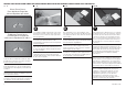
7 EP MOTOR INSTALLATION•E-MOTOR EINBAU•INSTALLATION DU MOTEUR EP•INSTALLAZIONE DEL MOTORE ELETTRICO 1 2 3 LL RR With the radio system on and servo centered, adjust the clevises so the ruddervators are centered. Once the linkage length has been set, tighten the nuts against the clevises to prevent them from vibrating loose. Justieren Sie mit zentrierter Fernsteuerung die Gabelköpfe so, dass die Ruder zentriert sind.
PROPELLER INSTALLATION•MONTAGE DES PROPELLERS•INSTALLATION DE L’HÉLICE•INSTALLAZIONE DELL’ELICA Î The following shows the installation of the EFLP12080PP (Plastic Propeller, 12 x 8) or EFLP12080CP (Carbon Propeller, 12 x 8) and EFLP12080S (Spinner Assembly). These items must be purchased separately as they are not included with the model.
Î Use extreme caution around the propeller, and check transmitter switch and throttle stick positions before connecting the motor battery. RECEIVER INSTALLATION•EMPFÄNGEREINBAU•INSTALLATION DU RÉCEPTEUR•INSTALLAZIONE DEL RICEVITORE 1 2 3 Î Sein Sie bitte extrem aufmerksam und vorsichtig im Umgang mit dem Propeller. Prüfen Sie die Position von Schaltern und dem Gashebel bevor Sie den Akku anschließen.
MOTOR BATTERY AND CANOPY INSTALLATION•EINSETZEN DES AKKUS UND DER KABINENHAUBE• INSTALLATION DE LA BATTERIE ET DE LA BULLE•INSTALLAZIONE BATTERIA E CAPOTTINA 1 2 3 WING INSTALLATION• MONTAGE DER TRAGFLÄCHEN• INSTALLATION DE L’AILE• MONTAGGIO DELL’ALA Using the remaining hook and loop tape and attach the loop portion to the bottom of the battery. Do not cover safety warnings with hook and loop tape. Place the battery in the fuselage.
2 4 RUDDERVATOR CONTROL THROW DIRECTIONS•RUDERAUSSCHLÄGE UND RICHTUNGEN•DÉBATTEMENT ET DIRECTION DES GOUVERNES• CONTROLLO CORSE ELEVATORE 1 Ruddervators centered• Leitwerk zentriert• Gouvernes centrées• Coda a V centrata Slide the wing tube into the wing tube socket. Schieben Sie den Flächenverbinder in die Öffnung an der Tragfläche. Faire glisser la clé d’aile dans le réceptacle du tube de l’aile. Inserire il tubo nella sua sede nell’ala.
3 Down Elevator• Höhenruder nach unten• Manche de profondeur vers le haut• Elevatore verso il basso Both the right and left ruddervators move down with an down elevator input at the transmitter. Beide Ruder Ruder bewegen sich nach unten mit der Steuereingabe Höhenruder nach unten. Les deux gouvernes doivent s’incliner vers le bas. Entrambi i semi piani si devono muovere verso il basso quando si dà il comando corrispondente sul trasmettitore.
CENTER OF GRAVITY DER SCHWERPUNKT CENTRE DE GRAVITÉ CENTRO DI GRAVITA’ (BARICENTRO) An important part of preparing the aircraft for flight is properly balancing the model. Ein sehr wichtiger Teil in der Flugvorbereitung ist es das Flugzeug richtig auszubalancieren. Une des étapes importantes de la préparation d’un modèle est son équilibrage. Un punto importante per preparare l’aereo al volo è quello di fare un centraggio corretto. 1.
CONTROL THROWS RUDERAUSSCHLÄGE 1. Turn on the transmitter and receiver of your model. Check the movement of the rudder using the transmitter. When the stick is moved to the right, the rudder should also move right. Reverse the direction of the servo at the transmitter if necessary. 1. Schalten Sie den Sender und Empfänger ihres Modells ein. Prüfen Sie die Seitenruderaussschläge mit dem Sender. Bewegen Sie den Seitenruderstick nach rechts, sollte sich das Ruder auch nach rechts bewegen.
DÉBATTEMENTS CORSE DEI COMANDI 1. Mettez l’émetteur et le récepteur sous tension. Contrôlez les mouvements de la dérive en utilisant votre émetteur. Quand le manche est vers la droite, la dérive doit s’orienter vers la droite. Inversez la direction du servo à l’émetteur si nécessaire. 1. Accendere trasmettitore e ricevitore del modello. Controllare i movimenti del timone agendo sul trasmettitore. Quando lo stick va a destra, anche il timone deve andare a destra.
PREFLIGHT CHECKLIST VORFLUGKONTROLLE CHECKLIST D’AVANT VOL LISTA DEI CONTROLLI PRIMA DEL VOLO • • • • Caricare le batterie di trasmettitore, ricevitore e accensione motore usando i caricabatterie consigliati o forniti con il radiocomando e seguendo le istruzioni. Caricare il radiocomando la notte prima di ogni sessione di volo. Seguire le istruzioni e le raccomandazioni fornite insieme alle apparecchiature elettroniche.
DAILY FLIGHT CHECKS TÄGLICHER FLUG CHECK CONTRÔLES SYSTÉMATIQUES CONTROLLI DI VOLO GIORNALIERI • • • • Check the battery voltage of the transmitter battery. Do not fly below the manufacturer’s recommended voltage. To do so can crash your aircraft. When you check these batteries, ensure you have the polarities correct on your expanded scale voltmeter. • Achten Sie bei dem Test darauf, dass die Polarität auf dem Voltmeter richtig angezeigt wird.
LIMITED WARRANTY What this Warranty Covers Limitation of Liability Inspection or Services Non-Warranty Service Horizon Hobby, Inc. (“Horizon”) warrants to the original purchaser that the product purchased (the “Product”) will be free from defects in materials and workmanship at the date of purchase.
GARANTIE UND SERVICE INFORMATIONEN Warnung Ein ferngesteuertes Modell ist kein Spielzeug. Es kann, wenn es falsch eingesetzt wird, zu erheblichen Verletzungen bei Lebewesen und Beschädigungen an Sachgütern führen. Betreiben Sie Ihr RC-Modell nur auf freien Plätzen un beachten Sie alle Hinweise der Bedienungsanleitung des Modells wie auch der Fernsteuerung. Garantiezeitraum Exklusive Garantie ¬ Horizon Hobby Inc (Horizon) garantiert, dass das gekaufte Produkt frei von Materialund Montagefehlern ist.
GARANTIE ET RÉPARATIONS Durée de la garantie Garantie exclusive - Horizon Hobby, Inc. (Horizon) garantit que le Produit acheté (le « Produit ») sera exempt de défauts matériels et de fabrication à sa date d’achat par l’Acheteur. La durée de garantie correspond aux dispositions légales du pays dans lequel le produit a été acquis. La durée de garantie est de 6 mois et la durée d’obligation de garantie de 18 mois à l’expiration de la période de garantie.
GARANZIA Periodo di garanzia Limiti di danno Manutenzione e riparazione La garanzia esclusiva - Horizon Hobby, Inc., (Horizon) garantisce che i prodotti acquistati (il “Prodotto”) sono privi di difetti relativi ai materiali e di eventuali errori di montaggio. Il periodo di garanzia è conforme alle disposizioni legali del paese nel quale il prodotto è stato acquistato. Tale periodo di garanzia ammonta a 6 mesi e si estende ad altri 18 mesi dopo tale termine.
WARRANTY AND SERVICE CONTACT INFORMATION•GARANTIE UND SERVICE KONTAKTINFORMATIONEN• COORDONNÉES DE GARANTIE ET RÉPARATIONS•GARANZIA E REVISIONA INFORMAZIONI PER I CONTATTI Country of Purchase Horizon Hobby Horizon Service Center (Repairs and Repair Requests) United States of America Horizon Product Support (Product Technical Assistance) servicecenter.horizonhobby.com/RequestForm/ www.quickbase.com/db/ bghj7ey8c?a=GenNewRecord 888-959-2305 sales@horizonhobby.co.
AMA NATIONAL MODEL AIRCRAFT SAFETY CODE Effective January 1, 2013 A. GENERAL: (h) Not operate model aircraft while under the influence of alcohol or while using any drug which could adversely affect the pilot’s ability to safely control the model. B. RADIO CONTROL (RC) 1. All pilots shall avoid flying directly over unprotected people, vessels, vehicles or structures and shall avoid endangerment of life and property of others. 7.
CONTROL THROW TOOL• EINSTELLLEHRE RUDERAUSCHLÄGE• OUTIL DE MESURE DU DÉBATTEMENT• ATTREZZO PER IL CONTROLLO DELLE CORSE EFL Allusive 2.
© 2014 Horizon Hobby, Inc. E-flite, Allusive, DSMX and Celectra are trademarks or registered trademarks of Horizon Hobby, Inc. The Spektrum trademark is used with permission of Bachmann Industries, Inc. All other trademarks, service marks and logos are the property of their respective owners.