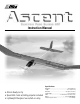
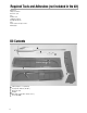
™ ™ Instruction Manual Specifications • Almost-Ready-to-Fly • Speed 400 motor w/folding propeller included • Lightweight fiberglass fuse w/bolt-on wing Wingspan............................................................ 54 in (1384 mm) Length .............................................................. 32 3⁄8 in (822 mm) Wing Area .................................................... 331 sq in (21.4 dm 2) Flying Weight .................................................... 19.5 oz (552.8 g) Radio .....
Table of Contents Introduction . . . . . . . . . . . . . . . . . . . . . . . . . . . . . . . . . . . . . . . . . . . . . . . . . . . . . . . . . . . . . . . . . . . . . . . . . . . . . . . . . . . . . . . . 4 Warning . . . . . . . . . . . . . . . . . . . . . . . . . . . . . . . . . . . . . . . . . . . . . . . . . . . . . . . . . . . . . . . . . . . . . . . . . . . . . . . . . . . . . . . . . . . 4 Radio Equipment Required. . . . . . . . . . . . . . . . . . . . . . . . . . . . . . . . . . . . . . . . . . . .
Introduction Thank you for purchasing the Ascent electric park glider. E-flite’s Ascent offers the modeler an ARF (almost-ready-to-fly) electric park glider that is pre-built to a high level of craftsmanship. It is unique in that it comes with the electric motor and folding propeller installed, complete with preassembled wiring harness, saving a significant amount of construction time.
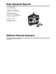
Radio Equipment Required • 3-channel radio system • 7- or 8-cell battery pack • Micro Receiver (JRPR610) • Sub-Micro Servos (2) (JRPS241) • 20-Amp Mini ESC w/Brake (EFLA105) Recommended JR System J-Line Quattro Lite System (JRPF404) (Quattro transmitter, JR R610M Receiver and 2 each JR 241 Sub-Micro Servos) ™ AirPac Micro (JRPF640) (JR R610M receiver and 2 each JR 241 sub-micro servos) ™ JRPF404 Additional Required Equipment 7- or 8-cell Ni-Cd battery pack 500–800mAh Battery charger 5
Required Tools and Adhesives (not included in the kit) Hobby knife Phillips screwdriver Hex Driver: 3/32" Drill Drill Bit: 1/16" Sandpaper (medium) Felt-tipped pen/pencil Ruler Double-sided foam tape or Velcro Masking tape ® Kit Contents B A C D E F A B C D E F 6 Folding Propeller, 7 x 3 (EFL1079) Fuselage with Tail Boom (EFL1077) Wing Joiner Tube Hardware Main Wing Set (EFL1076—includes item C) Tail Set (EFL1080)
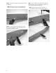
Section 1: Mounting the Wing Parts Needed B Ascent fuselage Right and left wing panel Aluminum wing tube Wing dowels (2) 4-40 x 1/2" hex screws (2) 4-40 washers (2) Tools and Adhesives Needed Hobby knife Hex Driver: 3/32" 6-minute epoxy Rubbing alcohol Paper towels Felt-tipped pen/pencil Step 1. Locate the right and left wing panels and the two 1" wing dowels. Test fit the dowels into the predrilled holes in the leading edge of each wing. Step 2.
Step 5. Slide the other wing panel onto the wing tube, joining the wing halves. Note: The wing of the Ascent™ is not glued together. The wing panels separate to allow for ease of transportation. Step 7. Secure the wing to the fuselage with the 4-40 x 1/2" wing mounting hex screws and 4-40 washers provided. Use a 3/32" hex driver to tighten the wing screws. Note: Remove the wing for now. You will need to reinstall it during the alignment of the horizontal stabilizer. A Step 6.
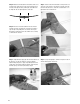
Section 2: Installing the Horizontal and Vertical Tail Surfaces Parts Needed Fuselage assembly Wing assembly Horizontal stabilizer w/elevator Vertical stabilizer w/rudder Tail boom skid Step 2. Place the horizontal stabilizer on the balsa wood saddle under the tail boom and align the two marks made in Step 1. The trailing edge of the tail boom should align with the hinge line, allowing the elevator to move up and down. Use masking tape to hold the horizontal stab to the boom.
Step 5. With the horizontal stabilizer still attached, make sure it is parallel to the main wing as shown in the illustration below. If needed, make adjustments by sanding the stab saddle until the wing and stab are aligned parallel to each other. Step 8. Slide the vertical fin and rudder assembly into the slot at the rear of the tail boom. The hinge line should be even with the back of the tail boom as shown. Also check that there is no gap between the fin and tail boom. A Step 6.
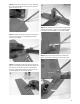
Step 10. Remove the fin from the boom. Using a sharp hobby knife, remove the covering from the fin tab just inside the lines drawn in the previous step. B Step 13. Once the epoxy has cured, locate the boom skid and mark its position on the bottom of the boom. The skid should be placed in line with the vertical fin 90 degrees to the horizontal stabilizer. Step 11. Carefully sand the tail boom inside the lines drawn in Step 9 to remove the paint. Use masking tape to protect the boom from the sandpaper.
Section 3: Installing the Elevator and Rudder Servos Parts Needed Fuselage assembly Sub-Micro Servos (2) (JRPS241) Step 3. Secure the servos in place using the mounting screws supplied with the servos. A Tools and Adhesives Needed Phillips head screwdriver Step 1. Install the mounting hardware (grommets & eyelets) supplied with your servos. Also remove the servo arms at this time. B Step 2. Install the servos into the preinstalled servo tray in the fuselage.
Section 4: Installing the Elevator and Rudder Control Horns and Linkages Parts Needed B Fuselage assembly Plywood control horns Quick connects (2) Control wires (2) Tools and Adhesives needed Hobby knife Pliers Phillips screwdriver Medium CA Rudder (right) Step 1. Locate the precut slot in the elevator and rudder. Carefully remove the covering over the slot using a sharp hobby knife. Step 3. Carefully slide the elevator and rudder control wires back into their respective housing in the boom.
Step 4. Locate the short servo control arm include with your servos. Install an easy connector onto the servo control arms as shown. Clip off the servo arms that are not used. Step 5. With the elevator and rudder centered and the servos at their neutral position, slide the easy connectors onto the control wires and secure the servo arms to the servos. The servo arm should be 90 degrees to the control wire. Note: It may be necessary to cut the control wires to allow the easy connectors to slide on.
Section 5: Installing the Speed Control and Receiver Parts Needed Fuselage assembly 20-Amp Mini ESC w/Brake (EFLA105) Micro Receiver (JRPR610) Step 3. Mount the switch using a Phillips screwdriver and the screws provided with the speed control. Tools and Adhesives Needed Drill Drill Bit: 1/16" Phillips screwdriver Clear tape Double-sided foam tape This section describes the installation of the E-flite™ Mini 20-Amp Electronic Speed Control (EFLA105).
Step 6. Run the receiver antenna out of the fuselage through one of the air exits and secure the antenna wire to the boom with clear tape. 16 Step 7. Secure the receiver to the fuselage with double-sided foam tape.
Section 6: Balancing the Control Throw Recommendations Parts Needed Assembled Ascent Park Glider Flight pack installed ™ Step 2. Place a strip of masking tape on either side of the wings lower surface, next to the fuselage. Mark the location of the CG 2 3⁄ 8" from the leading edge on the bottom of the wing on both sides of the fuselage.
Section 7: Preflight Checks Perform these preflight checks on your Ascent park glider before each flying session. Correct any issues before attempting to fly your plane.
Section 9: Thermal Soaring A key component to soaring is the air mass the park glider flies in. Also, there is an energy source producing lift, either a warm air thermal (thermal lift), or the wind rising as it meets an obstacle such as a hill or a line of mountains (ridge lift). We will limit our discussion to describing thermal soaring. We will be using the electric motor to launch our park glider to altitude.
As you are flying your Ascent™, watch it carefully. If you were in a full-size glider, you would be able to feel the "bump" of entering a thermal. Now you must depend on signs the glider gives as it approaches or enters a thermal. The second method is to make a wide 180-degree turn back into the thermal. When the Ascent flies near a thermal that is rising, the wing closest to the thermal will also try to rise, causing the aircraft to "rock" slightly.
Section 10: In-Flight Adjustments for Performance and Conditions • Pitch Attitude • Minimum Sink Speed • Maximum Lift/Drag (L/D) Speed • Best Penetration Speed Once the fundamentals of launch, trim, and control of the Ascent™ are learned, it's time to consider getting the most out of the it's ability to perform. To do that, one must learn how to trim your Ascent for maximum performance, whatever the current conditions are at the time.
AMA SAFETY CODE Model Flying MUST be in accordance with this Code in order for AMA Liability Protection to apply. General 1. I will not fly my model aircraft in sanctioned events, air shows, or model flying demonstrations until it has been proven to be airworthy by having been previously, successfully flight-tested. 2. I will not fly my model higher than approximately 400 feet within 3 miles of an airport without notifying the airport operator.
Notes 23
™ © Copyright 2002 Horizon Hobby, Inc. www.horizonhobby.