
EFL8750 E-flite AT-6 1.5m Manual


EN
5
Model Assembly
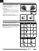
Horizontal Tail Installation
1. Insert the horizontal tail joiner tube (A) into the fuselage. Slide the horizontal
tail halves (B) into place with the control horn facing down.
2. Secure the horizontal tail piece in place using the included 2 screws (C). Use
care to avoid over-tightening the screw.
3. Attach the pushrod to the elevator control horn using the included clevis.
C
2 x 10mm
self-tapping
button head
A
B
B
Wing Installation
1. Install the wing to the bottom of the fuselage ensuring the hands-free servo
connection system is aligned.
2. Secure the wing using the included 4 x 8mm screws (C).
Disassemble in reverse order.
4 x 8mm
button head machine
B
1.
2.
3.
4.
5.
6.
Clevis Installation
• Pull the tube from the clevis to the linkage.
• Carefully spread the clevis, then insert the clevis pin into the desired
hole in the control horn.
• Move the tube to hold the clevis on the control horn.
Control Surface Centering
After assembly and transmitter setup, conrm that the control surfaces are
centered. If the control surfaces are not centered, mechanically center the
control surfaces by adjusting the linkages.
If adjustment is required, turn the clevis on the linkage to change the length of
the linkage between the servo arm and the control horn.
After binding a transmitter to the aircraft receiver, set the trims and sub-trims
to 0, then adjust the clevises to center the control surfaces.