Instruction Manual | Bedienungsanleitung | Manuel d’utilisation | Manuale di istruzioni Note: Attempting to fly the helicopter without completely reading the manual may cause injury to yourself and people in the vicinity, as well as damage to the helicopter. Hinweis: D er Versuch, den Helikopter zu fliegen, ohne das Handbuch vollständig zu lesen, kann Verletzungen an Ihnen selbst und Menschen in der Nähe, wie auch Schäden am Helikopter verursachen.
NOTICE All instructions, warranties and other collateral documents are subject to change at the sole discretion of Horizon Hobby, Inc. For up-to-date product literature, visit bladehelis.com and click on the support tab for this product.
Table of Contents Blade 120 SR RTF/BNF Introduction . . . . . . . . . . . . . . 3 Motor Control Test. . . . . . . . . . . . . . . . . . . . . . . . . . . . 9 Troubleshooting . . . . . . . . . . . . . . . . . . . . . . . . . . . . . 3 Understanding the Primary Flight Controls . . . . . . . . 10 Product Registration. . . . . . . . . . . . . . . . . . . . . . . . . . 3 Dual Rates. . . . . . . . . . . . . . . . . . . . . . . . . . . . . . . . 12 First Flight Preparation. . . . . . . . . . . . . . . . . .
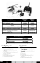
*Transmitter and AA Batteries not included with BNF Version Blade 120 SR Features Airframe – Blade 120 SR Main and Tail Motors – Brushed Ready-To-Fly Version Bind-N-Fly Version Included Included 2 Installed 2 Installed On-board Electronics – 5-in-1 receiver/servos/mixer/ ESCs/Gyro Installed Installed Battery – 1-cell 3.7V 500mAh Lithium Polymer (1.
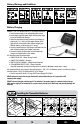
Battery Warnings and Guidelines 120F/49C Always use a charger compatible with batteries. Always charge Batteries away from flammable materials. Never leave charging Batteries unattended. Never Alter Batteries. Never charge damaged Batteries. Never touch or use hot Batteries. Battery Charging Celectra 1-Cell 3.7V Variable Rate DC Li-Po Charger Instructions 1. Connect power supply to an appropriate power source. 2.
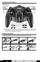
Transmitter Control Identification Mode 2/Mode 1 Rudder/Throttle Functions Rudder/Elevator Aileron/Elevator Functions Aileron/Throttle Rudder Trim Rudder Trim Throttle Trim Elevator Trim ON/OFF Switch Aileron Trim Aileron Trim Elevator Trim Throttle Trim Note: When pressed down, trim buttons make a sound that increases or decreases in pitch at each pressing. The middle or neutral trim position is heard as a middle tone in the pitch range of the sounds.
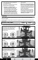
Transmitter and Receiver Binding If you purchased an RTF model, the transmitter is bound to the model at the factory. To bind or re-bind your 120 SR to your chosen transmitter please follow the directions below: Binding is the process of programming the receiver of the control unit to recognize the GUID (Globally Unique Identifier) code of a single specific transmitter. You need to ‘bind’ your chosen Spektrum™ or JR® DSM2 technology equipped aircraft transmitter to the receiver for proper operation.
process, the ESC or motors will be armed. Use caution because after arming, rotor blades will turn at throttle stick input. Note: If the 5-in-1 unit status LED does not glow solid RED, please review the following: • When the 5-in-1 unit status LED is off completely, you do not have a positive RF link between the transmitter and receiver. Make sure transmitter batteries and the flight battery are fully charged. Make sure the transmitter is powered on and that the transmitter LED glows solid red.
With the aileron stick pushed right, the righthand servo linkage should pull the swashplate downward. If at any time during the test the controls respond in the opposite direction, reverse/change the direction of operation of the flight controls. Follow these steps to change the direction of the various flight controls: 1. B e certain that battery is disconnected from the battery lead of the 5-in-1 control unit and the transmitter is turned off. 2.
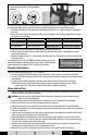
Understanding the Primary Flight Controls If you are not familiar with the controls of your 120 SR, take a few minutes to familiarize yourself with them before attempting your first flight. Transmitter Mode Legend The colored arrows correspond to the following transmitter modes: MODE 2 MODE 1 When the throttle stick is in the lowest possible position and throttle trim is set to the middle or a lower than the middle position, the main rotor blades will not spin.
Use rudder trim to help keep the nose of the helicopter from rotating left or right when in hover with no rudder stick input. For example, if the nose of the helicopter drifts to the right when in hover, add left rudder trim (by pressing and releasing the left rudder trim button) until the nose stays as near straight as possible. Forward The elevator stick controls both elevator (pitch fore/aft). Push the stick forward to pitch the nose of the helicopter down and fly forward.
Dual Rates Your 120 SR RTF model comes with the Blade MLP4DSM transmitter. This transmitter’s dual rate feature lets the pilot change between high and low control rates for the aileron, elevator, rudder and throttle channels. • When powered on, this transmitter is automatically in high-rate mode. • Change rate modes by pushing the right-hand control stick down into the case until it clicks while the transmitter is powered on. • High-rate mode is shown by the transmitter’s LED glowing solid red.
• W hile attempting to establish a low-level hover, you can also check to see if any trim adjustments are required to help keep the 120 SR from constantly drifting in various directions. If you find the helicopter constantly drifts without any directional control input, land the model before making any adjustments to the trim settings. Additional details regarding the location and function of the trim buttons are in the “Understanding the Primary Flight Controls” section of this manual.
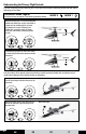
Exploded View and Parts Listings Note: Ball bearing (BLH3125) needs to face step Hinweis: Das Kugellager (BLH3125) on tail rotor (BLH3117). muß mit der Vorserseite zum Heckrotor zeigen (BLH3117).
Replacement Parts These parts are available at your local hobby shop or from Horizon Hobby (www.bladehelis.com). Please try your local hobby shop first. By supporting them, they will be there when you need them.
Optional Parts Number Description Number Description BLH3118R Complete Red Canopy with Grommets EFLC1005 AC to 6DC 1.5-Amp Power Supply BLH3120R Vertical Fin with Red Decal EFLC1006 Celectra 1S 3.7v Variable Rate DC Li-Po Charger BLH1065B Blade MLP4DSM 4CH Transmitter, 2.
Problem Possible Cause Possible Solution Aircraft tail control is intermittent. • Loose tail motor connectors. • Confirm tail motor connectors are firmly seated • Replace tail motor.
(c) Purchaser Remedy- Horizon’s sole obligation hereunder shall be that Horizon will, at its option, (i) repair or (ii) replace, any Product determined by Horizon to be defective. In the event of a defect, these are the Purchaser’s exclusive remedies. Horizon reserves the right to inspect any and all equipment involved in a warranty claim. Repair or replacement decisions are at the sole discretion of Horizon.
Country of Purchase Horizon Hobby Address Phone Number/ Email Horizon Service Center 4105 Fieldstone Rd Champaign, Illinois 61822 USA 877-504-0233 Units 1-4 Ployters Rd Staple Tye Harlow, Essex CM18 7NS, United Kingdom +44 (0) 1279 641 097 Hamburger Str. 10 25335 Elmshorn Germany +49 (0) 4121 46199 66 14 Rue Gustave Eiffel Zone d’Activité du Réveil Matin 91230 Montgeron +33 (0) 1 60 47 44 70 (Electronics and engines) United States productsupport@horizonhobby.
Instructions for Disposal of WEEE by Users in the European Union This product must not be disposed of with other waste. Instead, it is the user’s responsibility to dispose of their waste equipment by handing it over to a designated collection point for the recycling of waste electrical and electronic equipment.
HINWEIS Alle Anweisungen, Garantien und dazugehörigen Dokumente können ohne Ankündigung von Horizon Hobby, Inc. geändert werden. Eine aktuelle Version ersehen Sie bitte unter: http://www.bladehelis.com unter Support für dieses Produkt. Erklärung der Begriffe Die folgenden Begriffe erklären die Gefährdungsstufen im Umgang mit dem Produkt: Hinweis: Verfahren die nicht ordnungsgemäß durchgeführt werden, beinhalten die Möglichkeiten einer Beschädigung und maximal ein kleines Risiko einer Verletzung.
Inhaltsverzeichnis Blade 120 SR RTF/BNF Einleitung. . . . . . . . . . . . . . . . 3 Der Kanal 5 Drehknopf. . . . . . . . . . . . . . . . . . . . . . . . 9 Problemlösung. . . . . . . . . . . . . . . . . . . . . . . . . . . . . . 3 Motor Test. . . . . . . . . . . . . . . . . . . . . . . . . . . . . . . . . 9 Produktregistrierung. . . . . . . . . . . . . . . . . . . . . . . . . . 3 Beschreibung der Flugsteuerung . . . . . . . . . . . . . . . 10 Die Vorbereitung für den Erstflug. . . . . . . . . . . . . .
*Sender und AA Batterien sind nicht im Lieferumfang der BNF Version enthalten.
Battery Warnings and Guidelines ACHTUNG WARNUNG WARNUNG WARNUNG WARNUNG WARNUNG 120F/49C Verwenden Sie keines Falls ein Ni-Cd or Ni-MH Ladegerät. Laden Sie immer Akkus entfernt von brennbaren Stoffen auf. Laden Sie den Akku nie unbeaufsichtigt auf. Laden Sie niemals beschädigte Akkus auf. Fassen oder verwenden Sie niemals heisse Akkus an. Modifizieren Sie niemals Akkus. Laden des Flugakkus Celectra 1 S , 3,7 Volt einstellbares DC Li-Po Ladegerät 1. Verbinden Sie das Netzgerät mit Netzstrom. 2.
Sender Kontroll Identifikation Mode 2/Mode 1 Roll / Nick Funktion Roll / Gas Funktion Seitenruder / Gas-Pitch Funktion Seitenruder / Nick Funktion Seitenruder Trimmung Seitenruder Trimmung Gas Pitch Trimmung Nick Trimmung Ein / Aus Schalter Roll Trimmung Roll Trimmung Nick Trimmung Gas Pitch Trimmung Henweis: Drücken Sie die Trimmung herunter, hören Sie tiefer werdene Töne. Drücken Sie die Trimmung herauf, hören Sie höher werdene Tönen.
Binden von Sender und Empfänger Wenn Sie ein RTF Modell gekauft haben, ist der Sender ab Werk mit dem Modell gebunden. Um Ihren Blade 120 SR wieder mit dem Sender zu binden, gehen Sie bitte wie folgt vor. Binden ist der Prozess der Übermittlung eines senderspezifischen Signals (GUID Globally Unique Identifier), dass dann nur diesen Empfänger anspricht. Sie müssen zum Betrieb ihren gewählten Spektrum DSM2 Sender oder Modul mit dem Helikopter binden. Beschreibung des Bindeprozess A 1.
Hinweis: Sollte die Status LED nicht konstant Rot leuchten überprüfen Sie bitte folgendes: • Ist die Status LED auf dem 5-in-1 Controlboard aus, haben Sie keine RF Verbindung zwischen Sender und Empfänger. Stellen Sie sicher, dass der Sender eingeschaltet und der Flugakku vollständig geladen ist. Ist der Sender eingeschaltet und arbeitet einwandfrei, trennen Sie den Flugakku und verbinden ihn erneut. Das 5-in-1 Controlboard sollte sich nun initialisieren und armieren.
Wird der Stick nach rechts bewegt sollte das Servo auf der rechten Seite die Taumelscheibe nach unten drücken. Sollte während des Tests der Steuerung eine der Kontrollen in die falsche Richtung arbeiten, ist es notwendig die Laufrichtung zu reversieren (umzudrehen) Folgen Sie bitte dazu diesen Schritten. 1. Stellen Sie sicher das der Sender ausgeschaltet ist und der Flugakku nicht am 5-in-1 Board angeschlossen ist. 2. Drücken Sie den Trimmknopf der Funktion die Sie reversieren möchten.
Beschreibung der Flugsteuerung Wenn Sie mit der Steuerung des Blade 120 SR nicht vertraut sind, nehmen Sie sich vor Ihrem Erstflug bitte ein paar Minuten Zeit um sich mit ihr vertraut zu machen. Sender Mode Informationen Die zwei unterschiedlichen Pfeile erklären die beiden Steuermodes. MODE 2 MODE 1 Ist der Gas Stick in der untersten Position und die Trimmung unter der Mittelstellung drehen sich die Rotorblätter nicht.
Sie können die Trimmung des Seitenruders verwenden um die Nase des Helikopter im Schwebeflug zu stabilisieren. Dreht der Helikopter zum Beispiel im Schwebeflug nach rechts, geben sie etwas Trimmung nach links, bis der Helikopter nahezu gerade schwebt. Vorwärts Der Nick Stick steuert die Nick Funktion.
Dual Rates Der zur Ausstattung des Blade 120 SR RTF gehörende MLP4DSM Sender ist mit einer Dual Rate Funktion ausgestattet. Diese Funktion erlaubt es dem Piloten zwischen hohen oder niedrigen Steuerraten zu wählen . Diese Funktion ist verfügbar für die Kanäle der Roll, Nickfunktion, des Seitenruders und der Gasfunktion. Indem Sie den rechten Hebel des Senders eindrücken, können Sie bei eingeschalteten Sender zwischen hohen oder niedrigen Steuerraten wählen.
• W ährend Sie versuchen eine konstante Schwebeflughöhe zu halten, können Sie auch überprüfen ob das Modell konstant ohne eine Steuereingabe in eine Richtung wegdriften möchte. Landen Sie dann das Modell, trimmen die Funktion und starten dann wieder. Weitere Informationen über die Flugsteuerung und Trimmungen können Sie aus dem Kapitel: Die Flugsteuerung entnehmen. - Driftet die Nase des Hubschrauber nach links oder rechts müssen Sie die Trimmung des Seitenruders einstellen.
Exploded View and Parts Listings Hinweis: Das Kugellager (BLH3125) muß mit der Vorserseite zum Heckrotor zeigen (BLH3117). BLH3121 BLH3102 BLH3117 BLH3125 BLH3118 BLH3129 BLH3130 BLH3120 BLH3113 BLH3115 BLH3114 BLH3116 BLH3116 BLH3114 BLH3112 BLH3115 BLH3111 BLH3115 BLH3107 BLH3124 BLH3110 BLH3109 BLH3128 BLH3103 BLH3124 BLH3105 BLH3123 BLH3128 BLH3105 BLH3106 EFLB5001S BLH3101 BLH3104 BLH3108 BLH1066B BLH3127 Note: Not all wiring is shown.
Ersatzteile und optionale Teile Diese Teile erhalten Sie bei Ihrem Fachhändler oder bei Horizon Hobby. Bitte fragen Sie ihren Fachhändler zuerst. Unterstützen Sie ihn, wird er immer für Sie da sein wenn Sie Unterstützung benötigen.
Optionale Teile Nummer Beschreibung Nummer Beschreibung BLH3118R Kabinehauben Rot mit Befestigungen EFLC1005 6 Volt 1,5 Ampere Netzgerät BLH3120R Vertikale Finne mit roten Dekor EFLC1006 Celectra 1S 3,7 Volte einstellbares DC LiPo Ladegerät. BLH1065B Blade MLP4DSM 4 Kanal Sender 2,4 Ghz FUG4 4x AA Akkus Hilfestellung zur Problemlösung Problem möglicher Grund mögliche Lösung Hubschrauber reagiert nicht auf Gaseingabe, andere Funktionen arbeiten normal.
Problem möglicher Grund mögliche Lösung Unterbrecher in der Seitenruderfunktion • Wackelkontakt oder lose Heckrotoranschlüsse • Überprüfen Sie die Heckrotorverkabelung • Heckrotor defekt • Ersetzen Sie den Heckrotor Hubschrauber hovert selbständig in Kreisbewegung. • Beschädigte Rotorblätter • Ersetzen Sie die Rotorlätter • Fehlende oder lose Rotorkopfgestänge • Ersetzen Sie Rotorkopfgestänge (BLH3115) Hubschrauber driftet in eine bestimmte Richtung.
ohne Ankündigung zu ändern oder modifizieren und widerruft dann bestehende Garantiebestimmungen. (b) Horizon übernimmt keine Garantie für die Verkaufbarkeit des Produktes, die Fähigkeiten und die Fitness des Verbrauchers für einen bestimmten Einsatzzweck des Produktes. Der Käufer allein ist dafür verantwortlich, zu prüfen, ob das Produkt seinen Fähigkeiten und dem vorgesehenen Einsatzzweck entspricht.
behalten wir uns vor, das Produkt zu vernichten oder anderweitig zu verwerten. € Betreiben Sie Ihr Modell auf einem offenen Platz, weit ab von Verkehr, Menschen und Fahrzeugen. Achtung: Kostenpflichtige Reparaturen nehmen wir nur für Elektronik und Motoren vor. Mechanische Reparaturen, besonders bei Hubschraubern und RC-Cars sind extrem aufwendig und müssen deshalb vom Käufer selbst vorgenommen werden. € Betreiben Sie Ihr Fahrzeug nicht auf einer öffentlichen Straße.
Anleitung zur Entsorgung nach den WEEE Richtlinien bei der Verwendung innerhalb der Europäischen Union Dieses Produkt darf nicht mit anderem Schrott entsorgt werden. Stattdessen ist der Benutzer für die Entsorgung dessen Schrotts verantwortlich, indem er die Geräte zu einem bestimmten Sammelpunkt zum Recycling von Elektroschrott und elektronischer Geräte weitergibt.
NOTIFICATION Les instructions, garanties et autres documents afférents peuvent faire l’objet de modifications à tout moment par Horizon Hobby, Inc. Pour obtenir la dernière documentation en date, rendez-vous sur le site bladehelis.com et cliquez sur l’onglet Support de ce produit.
Table des matières Présentation du modèle Blade 120 SR RTF/BNF. . . . 41 Test de la commande moteur . . . . . . . . . . . . . . . . . . 47 Dépannage. . . . . . . . . . . . . . . . . . . . . . . . . . . . . . . . 41 Informations sur la voie 5. . . . . . . . . . . . . . . . . . . . . 47 Enregistrement du produit . . . . . . . . . . . . . . . . . . . . 41 Présentation des commandes pour le premier vol. . . 48 Préparation du premier vol. . . . . . . . . . . . . . . . . . . . 42 Doubles débattements. . .
*Émetteur et piles AA non fournis avec le modèle BNF.
Avertissements et recommandations concernant la batterie 120F/49C NeAlways jamais use charger a charger les accuscompatible au-delà des with recommandés batteries. niveaux Toujours charger les accus Always charge à l’écart de toute matière Batteries away from flammable materials. inflammable Ne jamais d’accus Neverlaisser leave en cours de charge sans charging Batteries surveillance unattended. Ne jamais toucher Never touch or ou utiliser d’accus use hot Batteries.
Présentation des commandes de l’émetteur Mode 2/Mode 1 Fonctions de direction/gaz Direction/ Profondeur Fonctions d’aileron/ de profondeur Aileron/Gaz Trim de direction Trim de direction Trim des gaz Trim de profondeur Bouton Marche/Arrêt Trim des ailerons Trim des ailerons Trim de profondeur Trim des gaz Installation de la batterie de vol Remarque : après avoir connecté la batterie de vol, maintenez l’hélicoptère immobile pour que le gyroscope puisse s’étalonner.
Affectation de l’émetteur au récepteur Si vous avez acheté un modèle RTF, l’émetteur a été affecté au modèle en usine. Pour affecter ou réaffecter votre 120 SR à votre émetteur, procédez comme suit : L’affectation désigne une opération qui consiste à programmer le récepteur de l’unité de contrôle pour qu’il reconnaisse le code unique d’affectation (GUID = Globally Unique Identifier) propre à l’émetteur.
de l’initialisation, les ESC ou les moteurs sont armés. Soyez prudent car, après l’armement, les pales du rotor se mettent à tourner au régime donné par la manette des gaz. Remarque : si le voyant d’état de l’unité 5 en 1 ne s’allume pas en rouge, vérifiez les points suivants : • Lorsque le voyant d’état de l’unité 5 en 1 est éteint, la liaison RF entre l’émetteur et le récepteur n’est pas satisfaisante. Vérifiez que les piles de l’émetteur et la batterie de vol sont complètement chargées..
Lorsque la manette des ailerons est poussée vers la droite, la liaison du servo droit doit abaisser le plateau cyclique. Si, pendant le test, les commandes de vol répondent dans la direction opposée, inversez/modifiez leur direction. Pour ce faire, procédez comme suit : 1. Vérifiez que la batterie est déconnectée de l’unité de contrôle 5 en 1 et que l’émetteur est hors tension. 2.
Présentation des commandes pour le premier vol Si vous êtes novice, prenez quelques minutes pour vous familiariser avec les commandes de votre 120 SR avant de tenter votre premier vol. Légende des modes de l’émetteur Les flèches de couleur correspondent aux modes suivants de l’émetteur : MODE 2 Lorsque la manette des gaz est dans la position la plus basse possible et que le trim des gaz est au milieu ou dans une position inférieure, les pales du rotor principal ne tournent pas.
Utilisez le trim de direction pour empêcher le nez de l’hélicoptère de tourner vers la gauche ou la droite en vol stationnaire, sans que la manette de direction soit actionnée. Par exemple, si le nez de l’hélicoptère dérive vers la droite en vol stationnaire, ajoutez du trim de direction (en appuyant sur le bouton de trim de direction gauche) jusqu’à ce que le nez reste aussi droit que possible. La manette de profondeur commande les deux gouvernes (tangage avant/arrière).
Doubles débattements Votre modèle 120 SR RTF est livré avec l’émetteur Blade MLP4DSM. La fonction de doubles débattements de cet émetteur permet au pilote de basculer entre des grands et petits débattements pour les voies d’aileron, de profondeur, de direction et des gaz. • Lorsqu’il est sous tension, cet émetteur est automatiquement en mode grands débattements. • Modifiez les modes de débattement en appuyant sur la manette de commande droite jusqu’à entendre le clic, lorsque l’émetteur est sous tension.
• L orsque vous tentez de tenir un vol stationnaire à faible hauteur, vous pouvez également vérifier s’il faut jouer des trims pour empêcher le 120 SR de dériver dans différentes directions. Si vous constatez que l’hélicoptère dérive constamment sans que la direction soit modifiée, faites atterrir le modèle et modifiez les réglages des trims. Pour en savoir plus sur l’emplacement et la fonction des boutons de trim, reportez-vous à la section Présentation des commandes pour le premier vol dans ce manuel.
Vue éclatée et liste des pièces Note: le roulement à billes (BLH3125) doit se trouver du côté du rotor de queue (BLH3117). BLH3121 BLH3102 BLH3117 BLH3125 BLH3118 BLH3129 BLH3130 BLH3120 BLH3113 BLH3115 BLH3114 BLH3116 BLH3116 BLH3114 BLH3112 BLH3115 BLH3111 BLH3115 BLH3107 BLH3124 BLH3110 BLH3109 BLH3128 BLH3103 BLH3124 BLH3105 BLH3123 BLH3128 BLH3105 BLH3106 EFLB5001S BLH3101 BLH3104 BLH3108 BLH1066B BLH3127 Note: Not all wiring is shown.
Pièces de rechange Ces pièces sont disponibles dans votre magasin de modélisme ou sur le site Horizon Hobby (www.bladehelis.com). Pour vos achats de pièces, adressez-vous d’abord à votre magasin de modélisme. Ainsi, il pourra vous fournir des pièces quand vous en aurez besoin.
Pièces de optionnelles Référence Description Référence Description BLH3118R Cabine Rouge complète avec caoutchoucs EFLC1005 Alimentation AC vers 6DC 1.5-Amp BLH3120R Dérive verticale avec décals EFLC1006 Chargeur LiPo Celectra 1S 3.7v Taux de charge variable BLH1065B Emetteur Blade MLP4DSM 4CH , 2.4GHz FUG4 4 piles AA Guide de dépannage Problème L’hélicoptère ne répond pas aux gaz, mais les autres commandes fonctionnent.
Problème L’hélicoptère vole en cercle, de sa propre initiative. Cause possible • Les pales du rotor sont endommagées. • La liaison avec la tête du rotor est manquante ou mal connectée. Solution possible • Remplacez les pales du rotor. L’hélicoptère semble dériver dans une certaine direction. • Le trim de direction n’était pas centré avant l’initialisation de l’hélicoptère. • Les commandes semblent inversées après une affectation à un émetteur différent.
Limitation des dégâts Horizon ne saurait être tenu pour responsable de dommages conséquents directs ou indirects, de pertes de revenus ou de pertes commerciales, liés de quelque manière que ce soit au produit et ce, indépendamment du fait qu’un recours puisse être formulé en relation avec un contrat, la garantie ou l’obligation de garantie. Par ailleurs, Horizon n’acceptera pas de recours issus d’un cas de garantie lorsque ces recours dépassent la valeur unitaire du produit.
Pays d’achat Horizon Hobby Adresse Numéro de téléphone/ Courriel France Horizon Hobby SAS 14 Rue Gustave Eiffel Zone d’Activité du Réveil Matin 91230 Montgeron +33 (0) 1 60 47 44 70 Déclaration de conformité conformément à la norme ISO/IEC 17050-1 No.
NOTA Tutte le istruzioni, le garanzie e gli altri documenti pertinenti sono soggetti a cambiamenti a totale discrezione di Horizon Hobby, Inc. Per una documentazione aggiornata sul prodotto, visitare il sito bladehelis.com e fare clic sulla sezione Support del prodotto.
Indice Introduzione a Blade 120 SR RTF/BNF. . . . . . . . . . . . 59 Presentazione dei principali comandi di volo. . . . . . . 66 Risoluzione dei problemi. . . . . . . . . . . . . . . . . . . . . . 59 Dual Rate. . . . . . . . . . . . . . . . . . . . . . . . . . . . . . . . . 68 Registrazione del prodotto . . . . . . . . . . . . . . . . . . . . 59 Scelta dello spazio per il volo . . . . . . . . . . . . . . . . . . 68 Preparazione al primo volo. . . . . . . . . . . . . . . . . . . . 60 Volo di 120 SR .
*Trasmittente e batterie AA non incluse con la versione BNF Versione RTF (Ready-To-Fly) Versione BNF (Bind-N-Fly) Inclusa Inclusa Motori principale e di coda - con spazzole 2 installati 2 installati Elettronica di bordo - 5 in 1 (ricevente/servo/mixer/ESC/ giroscopio) Installata Installata Batteria - Li-Po a 1 cella 3,7 V 500 mAh (1,9 Wh), 12C Inclusa Inclusa Caricabatteria - caricabatteria Li-Po a tensione CC variabile con adattatore CA Incluso Incluso Trasmittente - trasmittente a 4 can
Avvertenze e istruzioni per la batteria • Utilizzare sempre un caricabatterie compatibile con le batterie • Carica batterie sempre lontano da materiali infiammabili • Non effettuare la ricarica automatica • Non ricaricare le batterie danneggiate Never operate • Non modificare le batterie vehicle with • Non wiring. toccare né usare batterie hot damaged Carica della batteria Istruzioni per l’uso del caricabatteria Celectra Li-Po a tensione CC variabile 1 cella 3,7 V 1.
Identificazione dei comandi della trasmittente Modalità 2/Modalità 1 Funzioni timone/throttle Timone/Elevatori Funzioni alettoni/ elevatori Alettoni/Throttle Trim timone Trim timone Trim throttle Trim elevatori Interruttore ON/OFF Trim alettoni Trim alettoni Trim elevatori Trim throttle Nota: q uando vengono premuti, i pulsanti di trim emettono un segnale acustico dal tono crescente o decrescente a ogni pressione.
Binding della trasmittente e della ricevente Se è stato acquistato un modello RTF, il binding della trasmittente è stato già eseguito in fabbrica. Per eseguire o ripetere il binding di 120 SR alla trasmittente utilizzata, procedere nel modo descritto di seguito. Il binding consiste nella programmazione della ricevente dell’unità di controllo per fare in modo che riconosca il codice GUID (Globally Unique Identifier) di una particolare trasmittente.
❏❏ Appena il LED di stato dell’unità 5 in 1 emette una luce fissa ROSSA, l’unità di controllo è inizializzata ed è possibile procedere al volo. Inoltre, se lo stick e il trim del throttle sono impostati correttamente durante la procedura di inizializzazione, l’ESC o i motori sono azionati. Prestare attenzione perché dopo l’azionamento le pale del rotore iniziano a girare alla velocità impostata dallo stick del throttle.
Spingendo a destra lo stick degli alettoni, il leveraggio servo di destra deve abbassare la piastra di beccheggio. Se in qualsiasi momento durante il test la risposta dei comandi risulta invertita rispetto alla descrizione, invertire/ cambiare la direzione di funzionamento dei comandi di volo. Per cambiare la direzione di funzionamento dei vari comandi di volo, procedere come segue: 1. Accertarsi che la batteria sia scollegata dal cavo per la batteria dell’unità 5 in 1 e che la trasmittente sia spenta. 2.
Presentazione dei principali comandi di volo Prima di effettuare il primo volo, è opportuno acquisire familiarità con i comandi di 120 SR. Legenda delle modalità della trasmittente Le frecce colorate corrispondono alle seguenti modalità della trasmittente: MODALITÀ 2 Quando lo stick del throttle è impostato sulla posizione più bassa possibile e il trim del throttle è impostato sulla posizione intermedia o inferiore alla posizione intermedia, le pale del rotore principale non ruotano.
Utilizzare il trim del timone per evitare che la fusoliera dell’elicottero ruoti verso destra o sinistra durante il volo stazionario senza comandi forniti dallo stick del timone. Ad esempio, se la fusoliera dell’elicottero sbanda a destra durante il volo stazionario, aggiungere trim al timone a sinistra (premendo il pulsante del timone sul lato sinistro) fino a livellare il più possibile la fusoliera. Lo stick degli elevatori consente di controllare entrambi gli elevatori (passo avanti/indietro).
Dual Rate Il modello 120 SR RTF viene fornito con una trasmittente Blade MLP4DSM. La funzione Dual Rate di questa trasmittente consente al pilota di scegliere una velocità di controllo alta o bassa per i canali di alettoni, elevatori, timone e throttle. • All’accensione, questa trasmittente si trova automaticamente nella modalità alta.
• D urante il tentativo di stabilire un volo stazionario basso, è possibile inoltre verificare se sono necessarie regolazioni di trim per evitare che 120 SR sbandi in varie direzioni. Se si nota che l’elicottero sbanda continuamente senza rispondere ai comandi di direzione, farlo atterrare prima di regolare opportunamente le impostazioni di trim.
Vista esplosa ed elenco delle parti Note: Ball bearing needs to face step on tail rotor (BLH3117). BLH3121 BLH3102 BLH3117 BLH3125 BLH3118 BLH3129 BLH3130 BLH3120 BLH3113 BLH3115 BLH3114 BLH3116 BLH3116 BLH3114 BLH3112 BLH3115 BLH3111 BLH3115 BLH3107 BLH3124 BLH3110 BLH3109 BLH3128 BLH3103 BLH3124 BLH3105 BLH3123 BLH3128 BLH3105 BLH3106 EFLB5001S BLH3101 BLH3104 BLH3108 BLH1066B BLH3127 Note: Not all wiring is shown.
Parti di ricambio Queste parti possono essere acquistate presso un negozio di modellismo o direttamente da Horizon Hobby (www.bladehelis.com). Provare prima ad acquistarle presso un negozio di modellismo, il quale può garantirne una disponibilità più immediata.
Parti Opzionali Codice Descrizione Codice Descrizione BLH3118R Calotta completa EFLC1005 Adattatore di corrente da AC a DV 1.5-Amp BLH3120R Pinna verticale con decalcomania EFLC1006 Caricatore a controllo variabile per 1 cella a 3.7V Li-Po BLH1065B Blade MLP4DSM 4CH Transmitter, 2.
Problema Possibile causa Possibile soluzione Il modello tende continuamente a ruotare su se stesso o a sbandare in maniera indipendente • Trim del timone non centrato prima dell’inizializzazione del modello • Centrare il trim del timone e reinizializzare il modello • Trim non regolato in modo da compensare lo scaricamento della batteria durante il volo • Fare riferimento a Presentazione dei principali comandi di volo • Pala del rotore posteriore danneg giata • Sostituire la pala del rotore da
Limiti di danno Horizon non si riterrà responsabile per danni speciali, diretti, indiretti o consequenziali; perdita di profitto o di produzione; perdita commerciale connessa al prodotto, indipendentemente dal fatto che la richiesta si basa su un contratto o sulla garanzia. Inoltre la responsabilità di Horizon non supera mai in nessun caso il prezzo di acquisto del prodotto per il quale si chiede la responsabilità.
Dichiarazione di Conformità R&TTE (Secondo la norma ISO/IEC 17050-1) No. HH2010071001, HH2010071002 Prodotto: Blade 120 SR RTF, Blade 120 SR BNF Articolo: BLH3100, BLH3180 Dispositivo Classe: 1 L’oggetto della presente dichiarazione descritto sopraè in conformità con le caratteristiche delle specifiche elencate qui sotto, secondo la direttiva Europea R&TTE 1999/5/EC: EN 300-328 EN 301 489-1, 301 489-17 Requisiti generali di EMC EN 60950 Firmato per conto di: Horizon Hobby, Inc.
Created 5/10 bladehelis.