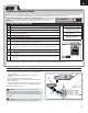
TM Carbon-Z Scimitar TM Instruction Manual - Bedienungsanleitung - Manuel d’utilisation - Manuale di Istruzioni
EN NOTICE All instructions, warranties and other collateral documents are subject to change at the sole discretion of Horizon Hobby, Inc. For up-to-date product literature, visit www.horizonhobby.com and click on the support tab for this product.
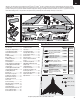
EN Welcome to the cutting edge of electric flight! Your E-flite® Carbon-Z™ Scimitar™ aircraft is a quantum leap in tailless swept wing design that combines patentpending Carbon-Z construction with the latest in high-output brushless motor and vector–thrust propeller engineering. The speed and maneuverability this makes possible is nothing short of spectacular. Read this manual thoroughly before taking your first flight. The Carbon-Z Scimitar can cover a lot of ground in a hurry.
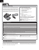
EN Charging the Flight Battery Your E-flite Carbon-Z Scimitar comes with a DC balancing charger and 4S Li-Po battery. You must charge the included Li-Po battery pack with a Li-Po specific charger only (such as the included charger). Never leave the battery and charger unattended during the charge process. Failure to follow the instructions properly could result in a fire. When charging, ensure the battery is on a heat-resistant surface. Charge the battery pack while you are assembling the aircraft.
EN Transmitter and Receiver Binding Binding is the process of programming the receiver of the control unit to recognize the GUID (Globally Unique Identifier) code of a single specific transmitter. You need to ‘bind’ your chosen Spektrum™ DSM2™/DSMX® technology equipped aircraft transmitter to the receiver for proper operation. Please visit www.bindnfly.com for a complete list of compatible transmitters. NOTICE: When using a Futaba transmitter with a Spektrum DSM® module, you must reverse the throttle channel.
EN Before Flight 1 • Lower throttle and throttle trim to lowest settings. 2 Power on Transmitter 3 • Connect battery to ESC. 4 • Power on ESC switch. Wait 5 seconds Continuous LED Series of tones Installing a Receiver 1. Install your full-range receiver in the fuselage using hook and loop tape or double-sided servo tape. 2. Attach the right aileron to the elevator channel of your receiver. Attach the left aileron to the aileron channel of your receiver. 3. Attach the Gear to channel 5. 4.
EN Fixed Landing Gear Installation Installing Nose Gear D C 1. Connect the linkage (A) to the steering servo arm (B). Always ensure the steering linkage clevis is adjusted correctly to make the model steer straight when the rudder control is at neutral. A 2. Connect the clevis (C) to the arm of the nose gear (D). 3. Install the nose gear plate (E) on the fuselage using five screws (F). NOSE GEAR B PARTS EXPLOSION F 3 X 8mm (5) E Installing Main Gear F 1.
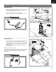
EN OPTIONAL Installing Optional Retractable Landing Gear This equipment is sold separately: • 10- to 15-Size Tricycle Electric Retracts (EFLG110) • Nose gear strut (EFL1018017) A Changing Stock Scimitar Nose Strut (EFL1018017) to Retractable Nose Gear Use of the nose gear strut included with the electric retracts does not let the nose gear retract into the fuselage well. B 1.
EN OPTIONAL Installing Optional Retractable Landing Gear (Continued) Installing Retractable Main Gear 1 2 3 4 5 • Install the Scimitar rear wheels (A) on the retract shafts (B) using the collars (C) and setscrews (D). • Loosely fit the shafts (B) on the rear landing gear struts (E) using two screws (F). • Remove Main Gear Plate (G) from the fuselage by removing 12 screws (H). • Put the retracts in the fuselage.
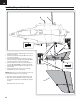
EN Installing Wings and Vertical Fins RUD A AILE B H E 3 X 12mm (4) G D 2.5 X 14mm (2) NOTICE: Always put excess connector wire into the pocket of the wing to prevent pinching of wires or other damage. 7. Turn over the model so the bottom of the fuselage faces up. 8. Make sure the left and right wings are fully in contact with the fuselage, then install the four screws (H) in the wing and fuselage. Disassemble the model in reverse order. 10 RUD AILE RUD AILE C 1.
EN Balancing the Propeller NOTICE: Because of the Vector Thrust on the Scimitar, the propeller must be precisely balanced to prevent excess vibration and damage to the vector thrust servo. Front Your propeller needs to be balanced before you install it on your airplane. Balancing a propeller prevents motor and/or airframe damage. Always balance a new propeller before use. The following procedure applies to propellers of all brands and materials e.g., plastic, wood, carbon fiber.
EN Opening the Fuselage 1 • Lift the front edge of the canopy (A) then pull the canopy forward and off the fuselage. • Loosen the screw (B) from the front of the receiver hatch (C), then lift the front edge of the receiver hatch and pull it forward and off the fuselage (carefully moving the tabs from under the retainers). 1 A B 3 X 10mm 2 C • Remove four screws (D) and the motor hatch (E) from the fuselage. Remove these hatches when setting up the Scimitar. Replace these hatches before checking CG.
EN Control Centering • Make sure servo directions (reversing) on your transmitter are correct. Ensure control surfaces move freely by performing a Control Test. • Make sure trim and sub-trims are set to zero. • Make sure the servo arms are set to 90 degrees. If not, remove a servo arm and put the arm in a spline position closest to the 90 degree position (perpendicular to the servo’s long axis).
EN Factory Settings Fly the model at factory settings before making changes. For pilots who wish for more control throw, adjust the position of linkages on servo arms and control horns for increased travel. Arms Nose Gear Vectored Thrust (VT) Elevons Rudder Transmitter Setup CAUTION: For safe operation, always re-bind the airplane after setup is complete to ensure the failsafe is updated with the latest setup.
EN Model Setup-Control Throws Rudders Measure from the center line (A) of the sub-fin to the rear lower tip of a rudder (B) to calculate the distance from the center of travel for the rudders. Vectored-Thrust (VT) Unit A Remove the motor hatch and look at the VT unit when adjusting mixes or travel for the AUX1 channel in your transmitter. Start with 100% Aux 1 servo travel, but a low % value in your programmable mixing (for example, 80%).
EN Center of Gravity (CG) CG is generally located at 553mm to 565mm from the front end of the aircraft. Flying wings like the Scimitar are more sensitive to changes in CG. Not using the recommended CG position may result in a variable or overall poor performance in some areas of the flight envelope. 553–565mm From the front end of the aircraft. To start, place the recommended 3200mAh battery all the way forward in the fuselage. Hold the battery in place using the front and middle hook and loop straps.
EN Preflight Checklist 1. Charge flight battery. 5. Adjust flight controls and transmitter. 2. Install flight battery in the aircraft (once it has been fully charged). 6. Perform a radio system Range Check. 7. Find a safe and open area. 3. Make sure linkages move freely. 8. Plan flight for flying field conditions. 4. Perform Control Direction Test with the transmitter. Flying Tips Range Check your Radio System After final assembly, range check the radio system with the E-flite Scimitar.
EN MAINTENANCE Fuselage Nose Service 1. Remove the canopy and battery from the fuselage. 2. Remove four screws (A), two in the plate in the bottom of the battery compartment and two on the left and right sides inside the fuselage. 3. A small amount of glue holds the nose on the fuselage, take care in removing it from the fuselage. 4. Replace nose using the four screws and a small amount of CA. A 2.5 X 10mm (4) MAINTENANCE Control Surface Service 1.
EN MAINTENANCE Servo Service Nose Gear 1. 2. 3. 4. Remove the three screws (A) from the steering servo. Remove the steering linkage from the servo arm. Remove the servo from the fuselage Disconnect the servo connector from the servo extension in the fuselage. Assemble in reverse order. A 2.5 X 8mm (3) Wing 1. Remove the wing from the model. 2. Remove the two screws (B) and aileron servo cover from the wing. 3. Remove the linkage (C) from the servo arm. 4.
EN MAINTENANCE Sub-Fin Service 1. Turn over the model so the bottom faces up. 2. Remove the six screws and sub-fin from the fuselage. Assemble in reverse order. 2.5 X 10mm (6) MAINTENANCE Motor and Vectored-Thrust Service Disassembly Assembly 1. 2. 2. 3. Assemble in reverse order, aligning wire colors of the motor with the ESC for correct operation. Remember to use threadlock. 4. 5. 6. 7. Open the fuselage. Remove the 12 screws (A) and upper motor housing (B) from the model.
EN Troubleshooting Guide Problem Aircraft will not respond to throttle but responds to other controls Possible Cause Throttle is not at idle and/or throttle trim is too high Solution Reset controls with throttle stick and throttle trim at lowest setting Throttle servo travel is lower than 100% Make sure throttle servo travel is 100% or greater Throttle channel is reversed Reverse throttle channel on transmitter Extra propeller noise or extra vibration Damaged propeller and spinner, collet or motor
EN AMA National Model Aircraft Safety Code Effective January 1, 2011 A. GENERAL A model aircraft is a non-human-carrying aircraft capable of sustained flight in the atmosphere. It may not exceed limitations of this code and is intended exclusively for sport, recreation and/or competition. All model flights must be conducted in accordance with this safety code and any additional rules specific to the flying site. 1. Model aircraft will not be flown: (a) In a careless or reckless manner.
EN Limited Warranty What this Warranty Covers Horizon Hobby, Inc. (“Horizon”) warrants to the original purchaser that the product purchased (the “Product”) will be free from defects in materials and workmanship at the date of purchase.
EN Contact Information Country of Purchase Horizon Hobby Address Phone Number/Email Address Horizon Service Center (Electronics and engines) 4105 Fieldstone Rd Champaign, Illinois 61822 USA 877-504-0233 Online Repair Request: visit www.horizonhobby.com/service Horizon Product Support (All other products) 4105 Fieldstone Rd Champaign, Illinois 61822 USA 877-504-0233 productsupport@horizonhobby.
Parts Contact Information • Kontaktinformationen für Ersatzteile • Coordonnés pour obtenir de piéces détachées • Recapiti per i ricambi Country of Purchase Horizon Hobby Address Phone Number/Email Address United States of America Sales 4105 Fieldstone Rd Champaign, Illinois 61822 USA 800-338-4639 Sales@horizonhobby.com United Kingdom Horizon Hobby Limited Units 1-4 Ployters Rd Staple Tye Harlow, Essex CM18 7NS United Kingdom +44 (0) 1279 641 097 sales@horizonhobby.co.
IT Replacement Parts • Ersatzteile • Piéces de rechange • Pezzi di ricambio Part # | Nummer Numéro | Codice Description Beschreibung Description Descrizione EFL1018017 Nose Strut Retract: C-Z Scimitar Einziehbares Bugstrebenfahrwerk: C-Z Scimitar Jambe du nez rétractable : C-Z Scimitar Elemento retrattile della gamba ammortizzatrice in punta: C-Z Scimitar EFLP1008E 10 X 8 Electric Propeller: C-Z Scimitar 10 X 8 elektrischer Propeller: C-Z Scimitar Hélice électrique 10 x 8 : C-Z Scimitar Elica
Optional Parts • Optionale Bauteile • Piéces optionnelles • Pezzi opzionali Part # | Nummer Numéro | Codice Description Beschreibung Description Descrizione EFLG110 10 - 15 Size Tricycle Electric Retracts by E-fl ite Elektrisch einziehbares dreirädriges Fahrwerk von E-flite, Größe 10-15 Trains rétractables électriques tricycles de taille 10 à 15 par E-flite Elementi retrattili elettrici triciclici, formato 10 - 15, di E-flite EFLA261 Micro/Mini Heli Tool Assortment Micro/Mini-Helikopter-Werkzeugsatz
© 2011 Horizon Hobby, Inc. E-flite, Carbon-Z, Scimitar, JR, DSM, DSM2, DSMX, ModelMatch, Bind-N-Fly, Z-Foam and Plug-N-Play are trademarks or registered trademarks of Horizon Hobby, Inc. The Spektrum trademark is used with permission of Bachmann Industries, Inc. Futaba is a registered trademark of Futaba Denshi Kogyo Kabushiki Kaisha Corporation of Japan. Patents Pending www.E-fliterc.