Instruction Manual Bedienungsanleitung Manuel d’utilisation Manuale di Istruzioni SAFE® Select Technology, Optional Flight Envelope Protection
EN NOTICE All instructions, warranties and other collateral documents are subject to change at the sole discretion of Horizon Hobby, LLC. For up-to-date product literature, visit www.horizonhobby.com or towerhobbies.com and click on the support or resources tab for this product.
EN Quick Start Information 1. Blank (Acro) Model 2. Wing Type: 1 Aileron, 1 Flap Transmitter Setup 3. Servo Reversing: Flaps Reversed, All Others Normal 4. Travel Adjust (All Surfaces): 100% High Rate = 15mm Aileron = 15mm Dual Rates = 40mm Elevator = 34mm = 28mm Rudder = 28mm High Rate Low Rate EXPO Aileron 10% 5% Elevator 10% 5% (Soft center) Rudder 10% 5% 115–150mm back from the leading edge, Center of Gravity (CG) measured at the wing root Flight Timer Setting 3.
EN Transmitter Setup (BNF) IMPORTANT: After you set up your model, always rebind the transmitter and receiver to set the desired failsafe positions. Computerized Transmitter Setup (DX6i, DX6e‡, DX6‡, DX7, DX7S, DX8, DX9, DX10t, DX18, DX20 and iX12) If your transmitter allows it, enable the throttle cut feature. Always engage throttle cut before approaching the aircraft. Start all transmitter programming with a blank ACRO model (do a model reset), then name the model.
EN Using SAFE® Select With the DX6 and DX6e Transmitters With a 6 Channel Aircraft The SAFE Select switch must be assigned to the Flap switch (switch D) BEFORE proceeding to the Transmitter Setup and should start from a blank (reset) model. Failure to assign the SAFE switch prior to programming the other model functions may prevent the SAFE switch from assigning correctly. Users of the DX6 and DX6e will have the SAFE Select functionality linked to the flaps.
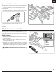
EN Model Assembly (Continued) Vertical Fin Installation (Continued) 1. Secure each fin with two M3 x 16 mm flathead screws through rear fin braces, as shown. Do not over tighten the screws. Horizontal Tail Installation 1. With the bottom of the fuselage facing up, slide the threaded hole end of the torque rod into the hole at the rear of the fuselage. Ensure the flat spot on the opposite end of the torque rod is facing up. 2. Secure the torque rod to the fuselage with a M3 x 10 mm flathead screw. 3.
EN Wing Installation 1. Center the wing tube in the tube socket in the fuselage. 2. Slide the right wing over the tube, ensuring the tube slides fully into the wing socket. 3. Align the servo connectors at the rear of the wing with the connectors in the fuselage, and ensure the fuselage alignment pins slide into the holes in the wing. 4. When fully seated against the fuselage, secure the wing with two M3 x 16mm flathead screws through the bottom of the wing, into the fuselage alignment pins. 5.
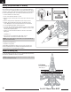
EN Nose Cone Installation 1. Align the nose cone with the front of the fuselage and slide the nose cone into place. Magnets will secure the nose cone to the fuselage. TIP: The pitot tube on the nose cone can be easily removed if desired, simply twist and un-thread until removed. Tail Cone Installation 1. Carefully apply thin CA to the tail cone. 2. Align the tail cone with the tail of the fuselage and slide the tail cone into position.
EN Optional Scale Missiles Installation The included optional scale missiles are easily installed and removed without the use of tools. • The missile are installed on the inner wing and fuselage mounting points. To install the missiles: 1. Insert the tabs of the missiles in the enlarged end of the mounting point slots. 2. Slide toward the back of the aircraft to lock the tabs in the slots. To remove the missiles, slide them forward and pull the tabs out of the mounting slots.
EN Battery Installation and ESC Arming Battery Selection We recommend a 22.2V 5000–7000mAh 30–100C 6S LiPo battery with EC5™ or IC5™ connector for standard operation. If using a different battery, the battery should be of similar capacity, dimensions and weight to fit in the fuselage. Always be sure the model balances at the recommended CG with the battery chosen. 1. Lower the throttle to the lowest setting. 2. Power on the transmitter and wait 5 seconds. 3.
EN Battery Installation and ESC Arming This product requires an approved Spektrum™ DSM2®/DSMX® compatible transmitter. Visit www.bindnfly.com for a complete list of approved transmitters. The aircraft has an optional SAFE Select feature, which can be switched ON or OFF easily by binding in a specific manner as described below.
EN Dual Rates and Controls Throws Program your transmitter to set the rates and control throws to the values given. These values have been tested and are a good starting point to achieve successful flight. Aileron After flying, you may choose to adjust the values for the desired control response.
EN Control Direction Test Switch on the transmitter and connect the battery. Use the transmitter to operate the aileron and elevator controls. View the aircraft from the rear when checking the control directions. Transmitter command Control Surface Response Ailerons 2. Move the aileron stick to the right. The right aileron should move up and the left aileron down, which will cause the aircraft to bank right. Elevators Elevator 1. Move the aileron stick to the left.
EN AS3X Control Direction Test This test ensures that the AS3X® control system is functioning properly. Assemble the aircraft and bind your transmitter to the receiver before performing this test. Aircraft Movement AS3X Reaction 1. Raise the throttle to any setting above 25%, then lower the throttle to activate AS3X technology. 2. Move the entire aircraft as shown and ensure the control surfaces move in the direction indicated in the graphic.
EN Flying Tips and Repairs Consult local laws and ordinances before choosing a flying location. Range Check your Radio System NOTICE: After any impact, always ensure the receiver is secure in the fuselage. If you replace the receiver, install the new receiver in the same orientation as the original receiver or damage may result. Before you fly, range check the radio system. Refer to your specific transmitter instruction manual for range test information.
EN Post Flight 1 2 3 4 Disconnect the flight battery from the ESC (Required for Safety and battery life). Power OFF the transmitter. Remove the flight battery from the aircraft. Recharge the flight battery. 5 6 7 Repair or replace all damaged parts. Store the flight battery apart from the aircraft and monitor the battery charge. Make note of the flight conditions and flight plan results, planning for future flights.
EN AS3X® System Trouble Shooting Guide Problem Oscillation Inconsistent flight performance Incorrect response to the AS3X Control Direction Test Possible Cause Solution Damaged rotor or nose cone Imbalanced rotor Motor vibration Loose receiver Loose aircraft controls Worn parts Irregular servo movement Trim is not at neutral Sub-Trim is not at neutral Aircraft was not kept immobile for 5 seconds after battery connection Replace rotor or nose cone Balance the rotor Replace parts or correctly align fan
EN Replacement Parts Part # EFL01076 EFL01077 EFL01078 EFL01079 EFL01080 EFL01081 EFL01082 EFL01083 EFL01084 EFL01085 EFL01086 EFL01087 EFL01088 EFL01089 EFL01091 EFL01092 EFL01098 EFL01099 EFL01100 EFLA0880EC5 EFLA420 EFLA7012DF EFLG321L EFLG321N EFLG321R SPMA380 SPMA380R SPMSA450 SPMSA450R SPMAR636 18 Description Wing Set: Su-30 70mm EDF Fuselage: Su-30 70mm EDF Horizontal Stab Set: Su-30 EDF Vertical Stab Set: Su-30 70mm EDF Canopy: Su-30 70mm EDF Nose Cone: Su-30 70mm EDF Nose Gear Doors: Su-30 70mm
EN AMA National Model Aircraft Safety Code Effective January 1, 2014 A. GENERAL A model aircraft is a non-human-carrying aircraft capable of sustained flight in the atmosphere. It may not exceed limitations of this code and is intended exclusively for sport, recreation, education and/or competition. All model flights must be conducted in accordance with this safety code and any additional rules specific to the flying site. 1. Model aircraft will not be flown: (a) In a careless or reckless manner.
EN Limited Warranty What this Warranty Covers Horizon Hobby, LLC, (Horizon) warrants to the original purchaser that the product purchased (the “Product”) will be free from defects in materials and workmanship at the date of purchase.
EN FCC Information This device complies with part 15 of the FCC rules. Operation is subject to the following two conditions: (1) This device may not cause harmful interference, and (2) this device must accept any interference received,including interference that may cause undesired operation. CAUTION: Changes or modifications not expressly approved by the party responsible for compliance could void the user’s authority to operate the equipment.
©2019 Horizon Hobby, LLC. E-flite, Plug-N-Play, Bind-N-Fly, BNF, the BNF logo, DSM, DSM2, DSMX, Spektrum AirWare, EC5, IC5, AS3X, SAFE, the SAFE logo, ModelMatch, and the Horizon Hobby logo are trademarks or registered trademarks of Horizon Hobby, LLC. The Spektrum trademark is used with permission of Bachmann Industries, Inc. Futaba is a registered trademark of Futaba Denshi Kogyo Kabushiki Kaisha Corporation of Japan. All other trademarks, service marks and logos are property of their respective owners.