
User Manual
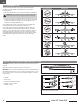
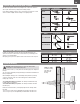

High Rate Low Rate
Aileron
p =11mm
q = 11mm
p = 7mm
q = 7mm
Elevator
p = 8mm
q = 11mm
p = 5mm
q = 8mm
Rudder
= 20mm
= 20mm
= 14mm
= 14mm
EN
15
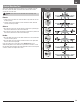
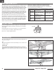
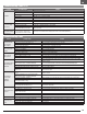
Control Horn and Servo Arm Settings
Factory Setting Control Horns Servo Arms
Elevator
E
A
R
E
A
R
Rudder
E
A
R
E
A
R
Aileron
E
A
R
E
A
R
Nose Gear
E
A
R
Tuning Control Horns Servo Arms
More control throw
Less control throw
The table to the right shows the factory settings for the control horns and servo
arms. Fly the aircraft at factory settings before making changes.
If you adjust the linkage positions for more control throw, then experience control
surface oscillation in flight, return the linkage to its original position.
Program your transmitter to set the rates and control throws based on your
experience level. These values have been tested and are a good starting point to
achieve a successful first flight.
After flying, you may choose to adjust the values for the desired control response.
Dual Rates and Control Throws
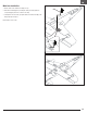
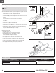
Warning: Install the battery but do not connect it to the ESC while
checking the CG. Personal injury may result.
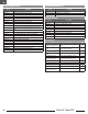
The CG location is 63mm (+/– 7mm) back from the leading edge of the wing at the
fuselage.
The CG location is adjusted by moving the battery pack forward or backward in the
battery compartment.
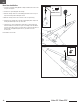
After installing the battery (in the recommended position) and before powering
on the ESC, verify the CG. The CG location starting point is 63mm behind the
leading edge, as shown.
3S 1300mAh Smart battery CG position – The battery is installed all the way
forward in battery compartment.
3S 2200mAh Smart battery CG position – The battery is installed centered in
the battery tray.
Balance the aircraft inverted on your fingertips adjacent to the fuselage under
the wings.
• If the nose goes down, move the flight battery back until the aircraft is level.
• If the nose goes up, move the flight battery forward until the aircraft is level.
63mm (+/– 7mm)
behind the leading
edge, where the
wing meets the
fuselage.
Center of Gravity
Nose Gear
Rudder