
User Manual

EN
Habu SS 50mm EDF
18
Service and Repairs
Power Components Service
CAUTION: Always disconnect the flight battery before performing motor
service.
Disassembly
The recommended power system components are given in the Specifications table
at the beginning of this manual.
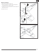
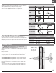
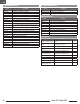
1. Remove the five screws and carefully remove the wing.
2. Remove the two screws (3 x 10) (A) from the fan unit mounting tabs.
3. Pull the fan unit (B) out of the fuselage and disconnect the motor leads from
the ESC.
Tip: label or mark the ESC and motor wires for reassembly. If a motor/esc wire
is reversed, the rotor will not operate in the correct direction.
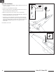
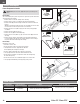
4. Remove the spinner screw (M2 x 14) (C) from the rotor by using a phillips
screwdriver.
5. Remove the spinner (D) from the rotor.
6. Remove the rotor (E), motor shaft adapter (F).
7. Remove the four screws (M2.5 x 6) (G) to remove the motor (H) from the fan
shroud (I).
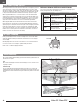
8. Remove the hook and loop strap and disconnect the throttle lead from the
receiver and pull the ESC (J) from the fuselage, taking note of the routing of
the power and throttle leads through the fuselage.
Disassembly
Assemble in reverse order.
• Assemble in reverse order.
• Ensure the spinner is fully connected for safe operation.
• Carefully tuck the motor/esc plugs under the EDF unit
before tightening the housing in the fuselage.
• Ensure no wiring is pinched by any of the power components.
• Correctly align and connect the motor wires with the ESC wires.
• Ensure the ESC is installed correctly and secured to the fuselage using
the hook and loop strap.
• Ensure the front of the rotor is installed facing the nose of the aircraft.
• Correctly align and install wing to fuselage using 5 wing screws.
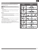
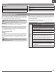
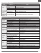
Control Surface Replacement Servo Description Replacement Adhesive
Aileron SPMSA345 A345 9g Sub-Micro Servo; 230mm Lead
Deluxe Materials Foam 2 Foam (DLMAD34)Elevator
SPMSA345SL A345SL 9g Sub-Micro Servo; 60mm Lead
Rudder
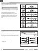
Servo Service
B
3 x 10mm
Self Tapping
Screw
A
D
M2 x 14mm
Machine Screw
C
E
F
I
H
M2.5 x 6mm
Machine Screw
G
J