T-28 Trojan 1.
EN NOTICE All instructions, warranties and other collateral documents are subject to change at the sole discretion of Horizon Hobby, LLC. For up-to-date product literature, visit horizonhobby.com or towerhobbies.com and click on the support or resources tab for this product.
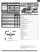
EN Quick Start Information Set up your transmitter Transmitter Setup using the transmitter setup chart High Rate Low Rate p = 14mm p = 10mm Aileron q = 14mm q = 10mm Dual Rates* p = 8mm p = 6mm Elevator q = 8mm q = 6mm = 19mm = 13mm Rudder = 19mm = 13mm 67 – 72mm behind the leading edge Center of Gravity (CG) of the wing at the fuselage Flight Timer Setting 5 minutes Box Contents Specifications Table of Contents Motor: 3226-930Kv 14-Pole Brushless Motor (SPMXAM1700) ESCs: 30A Telemetry-Capable ESC
EN SAFE® Select Technology BNF The BNF Basic version of this airplane includes SAFE Select technology which can offer an extra level of protection in flight. Use the following instructions to make the SAFE Select system active and assign it to a switch. When enabled, SAFE Select prevents the airplane from banking or pitching past predetermined limits, and automatic self-leveling keeps the airplane flying in a straight and level attitude when the aileron, elevator and rudder sticks are at neutral.
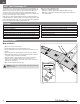
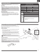
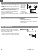
EN Model Assembly Landing Gear Installation A 1. Turn the model so the bottom of the wing faces up. 2. Install the main landing gear by inserting the main gear struts (A) into the corresponding gear plate hole located on each wing. 3. Carefully turn each strut in the gear plate until the horizontal section (B) of the strut gently snaps into place. 4. Loosen the nose gear screw (C) in the nose gear arm before installing the nose gear strut (D).
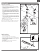
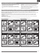
EN Model Assembly Control Horn and Servo Arm Settings The illustration shows recommended hole settings in the servo arms and control horns. Horns Arms Elevator Ailerons Rudder Rudder Nose gear Nose Gear Connect the clevises to the control horns as shown 1. 2. 3. 4. 6 T-28 Trojan 1.
EN Transmitter Setup BNF IMPORTANT: After you set up your model, always rebind the transmitter and receiver to set the desired failsafe positions. Dual Rates Attempt your first flights in low rate. For landings, use high rate elevator. NOTICE: To ensure AS3X technology functions properly, do not lower rate values below 50%.
EN Battery Installation and ESC Arming Battery Selection We recommend the Spektrum 2200mAh 14.8V 4S 30C Smart Li-Po battery (SPMX22004S30). Refer to the Optional Parts List for other recommended batteries. If using a battery other than those listed, the battery should be within the range of capacity, dimensions and weight of the Spektrum Li-Po battery packs to fit in the fuselage. Be sure the model balances at the recommended CG. 1.
EN General Binding Tips and Failsafe BNF • The included receiver has been specifically programmed for operation of this aircraft. Refer to the receiver manual for correct setup if the receiver is replaced. • Keep away from large metal objects while binding. • Do not point the transmitter’s antenna directly at the receiver while binding. • The orange LED on the receiver will flash rapidly when the receiver enters bind mode.
EN SAFE® Select Switch Designation BNF SAFE® Select technology can be assigned to any open switch (2 or 3 position) controlling a channel (5–9) on your transmitter. Once assigned to a switch, SAFE select ON gives you the flexibility to choose SAFE technology or AS3X mode while in flight. If the aircraft is bound with SAFE select OFF, the aircraft will be in AS3X mode exclusively.
EN Control Surface Direction Switch on the transmitter and connect the battery. Use the transmitter to operate the aileron, elevator, and rudder controls. View the aircraft from the rear when checking the control directions. Aileron stick Ailerons 1. Move the aileron stick to the left. The right aileron should move down and the left aileron up, which will cause the aircraft to bank left. 2. Move the aileron stick to the right.
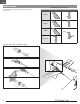
EN AS3X Control Response Test BNF This test ensures that the AS3X control system is functioning properly. Assemble the aircraft and bind your transmitter to the receiver before performing this test. 1. Raise the throttle to any setting above 25%, then lower the throttle to activate AS3X technology. Yaw Roll 2. Move the entire aircraft as shown and ensure the control surfaces move in the direction indicated in the graphic. If the control surfaces do not respond as shown, do not fly the aircraft.
EN Flying Tips and Repairs Consult local laws and ordinances before choosing a flying location. Flying Field Always choose a wide-open space for flying your aircraft. It is recommended you fly at a designated RC flying field. Always avoid flying near houses, trees, wires and buildings. Avoid flying in areas where there are many people, such as parks, schoolyards, or soccer fields. Range Check your Radio System Before you fly, range check the radio system.
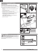
EN Motor Service CAUTION: Always disconnect the flight battery before performing motor service. Disassembly 1. 2. 3. 4. Use a tool to remove the spinner nut (A) from the collet (B). Remove the propeller (C), backplate (D) and collet from the motor shaft. Remove three screws (E) from the cowling (F). Carefully remove the cowling from the fuselage. Paint may keep the cowling attached to the fuselage. 5. Remove four screws (G) from the motor mount (H) and fuselage. 6.
EN Servo Service Wing Servo Removal 1. 2. 3. 4. 5. 6. 7. 8. 9. Remove the propeller. Remove the wing. Unplug the wing servo wires from the marked fuselage servo extensions. Flip the wing over, and set it on a smooth, soft surface. Remove the servo tape from the wing bottom of the damaged servo. Remove the pushrod clevis from the aileron control horn. Remove the tape strip covering the servo wire. Firmly pull on the servo to remove it from the wing. Remove the servo screw and the servo arm.
EN Troubleshooting Guide Problem Possible Cause Throttle not at idle and/or throttle trim too high Aircraft will not Throttle servo travel is lower than 100% respond to throttle but responds to other Throttle channel is reversed controls Motor disconnected from ESC Damaged propeller and spinner, collet or motor Extra propeller noise or Propeller is out of balance extra vibration Prop nut is too loose Flight battery charge is low Propeller installed backwards Reduced flight time or Flight battery damaged a
EN Replacement Parts Part # EFL08201 EFL08202 EFL08203 EFL08204 EFL08205 EFL08206 EFL08207 EFL08208 EFL08209 EFL08210 EFL08211 EFL08253 EFL08255 EFL08257 EFL08260 EFLA1030FB EFLP09575 SPMAR631 SPMSA381L SPMSA382 SPMXAM1700 Description Decal Sheet; T-28 Trojan 1.1m Canopy w/Pilot; T-28 1.1m Painted Wing; T-28 1.1m Horizontal Stab; T-28 1.1m Painted Cowl; T-28 1.1m Painted Fuselage; T-28 1.1m Motor Mount; T-28 1.1m Prop Adaptor; T-28 1.1m Landing Gear Plate; T-28 1.1m Pilot; T-28 Trojan 1.
EN Limited Warranty What this Warranty Covers Horizon Hobby, LLC, (Horizon) warrants to the original purchaser that the product purchased (the “Product”) will be free from defects in materials and workmanship at the date of purchase.
EN FCC Information FCC ID: BRWSPMSR6200A Supplier’s Declaration of Conformity T-28 Trojan 1.1m (EFL08250/EFL08275) This device complies with part 15 of the FCC Rules. Operation is subject to the following two conditions: (1) This device may not cause harmful interference, and (2) this device must accept any interference received, including interference that may cause undesired operation.
©2021 Horizon Hobby, LLC. E-flite, Plug-N-Play, Bind-N-Fly, BNF, the BNF logo, DSM, DSM2, DSMX, Spektrum AirWare, EC3, IC3, AS3X, SAFE, the SAFE logo, ModelMatch, and the Horizon Hobby logo are trademarks or registered trademarks of Horizon Hobby, LLC. The Spektrum trademark is used with permission of Bachmann Industries, Inc. All other trademarks, service marks and logos are property of their respective owners. US 8,672,726 US 9,056,667 US 9,753,457. US 10,078,329. US 9,930,567. US 10,419,970.