
User Manual


EN
T-28 Trojan 1.1m
4
Preflight
SAFE
®
Select Technology BNF
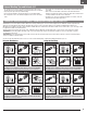
The BNF Basic version of this airplane includes SAFE Select technology which can
offer an extra level of protection in flight. Use the following instructions to make the
SAFE Select system active and assign it to a switch. When enabled, SAFE Select
prevents the airplane from banking or pitching past predetermined limits, and
automatic self-leveling keeps the airplane flying in a straight and level attitude when
the aileron, elevator and rudder sticks are at neutral.
SAFE Select is enabled or disabled during the bind process. When the airplane is
bound with SAFE Select enabled, a switch can be assigned to toggle between SAFE
Select mode and AS3X mode. AS3X
®
technology remains active with no bank angle
limits or self leveling any time SAFE Select is disabled or OFF.
SAFE Select can be configured three ways;
• SAFE Select Off: Always in AS3X mode
• SAFE Select On with no switch assigned: Always in SAFE Select mode
• SAFE Select On with a switch assigned: Switch toggles between SAFE Select
mode and AS3X mode
1. Remove and inspect contents.
2. Read this instruction manual thoroughly.
3. Charge the flight battery.
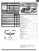
4. Setup Transmitter using transmitter setup chart.
5. Fully assemble the airplane.
6. Install the flight battery in the aircraft (once it has been fully charged).
7. Check the Center of Gravity (CG).
8. Bind the aircraft to your transmitter.
9. Make sure linkages move freely.
10. Perform the Control Direction Test with the transmitter.
11. Perform the AS3X Control Direction Test with the aircraft.
12. Adjust flight controls and transmitter.
13. Perform a radio system Range Test.
14. Find a safe open area to fly.
15. Plan flight for flying field conditions.
Model Assembly
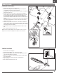
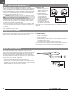
Wing Installation
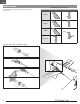
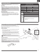
1. Remove the canopy from the fuselage.
2. Turn the wing and fuselage so their bottom sides face up.
3. Place the wing’s aileron servo connectors (A) into the rectangular hole in the
fuselage.
4. Slide the two guide pins (B) of the wing into the two holes in the fuselage.
5. Align and attach the wing to the fuselage using the included M3 x 25mm(C)
screw using a Phillips screwdriver (not included).
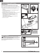
6. Inside the fuselage, connect both aileron servo connectors to the aileron
Y-harness. There is no difference between the two connections on a
Y-harness. Left and right servo connectors do not have to be connected to a
particular side of a Y-harness.
7. When needed, disassemble in reverse order.
CAUTION: DO NOT crush or otherwise damage wiring when attaching the
wing to the fuselage.
M3 X 25mm
C
B A