
User Manual


EN
5
Model Assembly
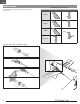
Landing Gear Installation
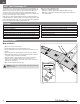
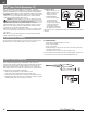
1. Turn the model so the bottom of the wing faces up.
2. Install the main landing gear by inserting the main gear struts (A) into the
corresponding gear plate hole located on each wing.
3. Carefully turn each strut in the gear plate until the horizontal section (B) of the
strut gently snaps into place.
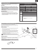
4. Loosen the nose gear screw (C) in the nose gear arm before installing the
nose gear strut (D). The screw may be fully installed at the factory, so loosen
the screw enough to ensure the screw does not block the strut. A hole in
the cowling allows a screwdriver to be used to turn the screw on the nose
gear arm using a #2 Phillips screwdriver that is at least 6”(155mm) long (not
included).
If more maneuvering space is needed, remove the propeller and cowling from
the model before installing the nose gear (as shown in the “Motor Service”
section of this manual).
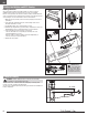
5. Install the nose gear strut so the flat surface of the strut faces forward. The
coil in the nose gear strut should face the rear of the airplane. Fully insert the
nose gear strut into the nose gear arm. When inserted, the top of the strut will
touch the upper portion of the firewall.
6. Fully tighten the nose gear screw against the flat surface of the nose gear
strut.
7. When needed, disassemble in reverse order.
Always ensure the steering linkage clevis on the rudder servo arm is correctly
adjusted so the model steers straight when the rudder control is at neutral.
A
D
C
B
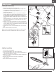
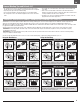
Stabilizer Installation
1. Place the model on its landing gear.
2. Turn the horizontal stabilizer so the control horn faces down.
3. Slide the horizontal stabilizer in the mount from the right hand side until it is
centered and perpendicular to the fuselage.
4. Apply 4 pieces of tape (A) on the fuselage mounts and the top and bottom of
the horizontal stabilizer.
5. Attach the clevis to the elevator control horn (see instructions for
clevis connection).
6. When needed, disassemble in reverse order.
A