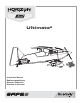
Ultimate 2 Instruction Manual Bedienungsanleitung Manuel d’utilisation Manuale di Istruzioni
EN NOTICE All instructions, warranties and other collateral documents are subject to change at the sole discretion of Horizon Hobby, LLC. For up-to-date product literature, visit www.horizonhobby.com and click on the support tab for this product.
EN Box Contents Quick Start Information Transmitter Setup Transmitter setup is required. Refer to the transmitter setup section in this manual. Center of Gravity (CG) 89mm back from leading edge at the center of the top wing. Flight Timer Setting 5 minutes Specifications Table of Contents 10BL Brushless outrunner 1300Kv Included 40-Amp Brushless ESC Installed (4) 13 g Digital Servo (EFLA1040U) Installed Spektrum™ AR636, 6-Channel Sport Receiver Installed Battery: 2200mAh 11.
EN Preflight 1 Remove and inspect contents. 9 2 Read this instruction manual thoroughly. 10 Perform the Control Direction Test with the transmitter. Make sure linkages move freely. 3 Charge flight battery. 11 Perform the AS3X Control Direction Test with the aircraft. 4 Setup Transmitter using transmitter setup chart. 12 Adjust flight controls and transmitter. 5 Fully assemble airplane. 13 Perform a radio system Range Test.
EN Transmitter Setup for this SAFE® Technology Aircraft It is extremely important to folow these transmitter setup charts to assign your transmitter switches correctly to operate the flight modes and Panic Recovery correctly. The installed AR636 receiver has been programmed for operation specifically in this aircraft. The flight modes can be changed in flight using a toggle switch (Gear/Channel 5 Switch).
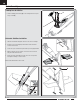
EN Model Assembly Landing Gear Installation B 1. Install the landing gear assembly (A) on the fuselage and secure in place using 3 screws (B). A Horizontal Stabilizer Installation 1. Slide the horizontal tail tube (A) into the hole in the rear of the fuselage. 2. Install the 2 piece (left and right) horizontal tail as shown. Ensure the control horn faces down. A 3. Secure the 2 piece horizontal tail in place with 4 pieces tape (B) included. 4.
EN Model Assembly Continued Wing Installation Bottom Wing Installation 1. Connect the aileron servo connectors (A) to the respective connectors in the fuselage. Right aileron servo to port 2 in the receiver and the left aileron into port 6. 2. Align the bottom wing mounting pins with the fuselage mounting plate to attach the bottom wing to the fuselage. 3. Secure the wing in place with the locking pin (B). Insert pin and turn 90 degrees to lock in place. A B Top Wing Installation 1.
EN Model Assembly Continued 3. Slide the left and right wing strut in place, between the upper and lower wings as shown. Ensure that the logo on the strut is facing out. 4. Secure the wing struts to the top and bottom wing with the 4 included pins (A). Ensure that the wing pins are fully seated. 5. Link the upper and lower ailerons by installing the Z-bend end (B) to the lower wing’s aileron control horn. 6. Center the lower aileron and adjust the ball link as needed so the top aileron is centered. 7.
EN Control Surface Centering After assembly and transmitter setup, confirm that the control surfaces are centered. If the control surfaces are not centered, mechanically center the control surfaces by adjusting the linkages. IMPORTANT: DO NOT use sub-trim and trim to center control surfaces. The AS3X system requires sub-trim and trim set at 0. After binding a transmitter to the aircraft receiver, set the trims and sub-trims to 0, then adjust the linkages to center the control surfaces.
EN Transmitter and Receiver Binding Binding is the process of programming the receiver to recognize the GUID (Globally Unique Identifier) code of a single specific transmitter. You need to ‘bind’ your chosen Spektrum™ DSM2®/DSMX® technology equipped aircraft transmitter to the receiver for proper operation. IMPORTANT: Before binding a transmitter, read the Transmitter Setup section of this manual to ensure that your transmitter is properly programmed for this aircraft.
EN Battery Installation and ESC Arming Battery Selection A We recommend the E-flite® 2200mAh 11.1V 3S 30C Li-Po battery (EFLB22003S30). Refer to the Optional Parts List for other recommended batteries. If using a battery other than those listed, the battery should be within the range of capacity, dimensions and weight of the E-flite Li-Po battery packs to fit in the fuselage. Be sure the model balances at the recommended CG. P 1. Lower the throttle and throttle trim to the lowest settings.
EN Center of Gravity (CG) The CG location is measured from the leading edge at the center of the top wing.This CG location has been determined with the recommended Li-Po battery (EFLB22003S30) installed. 89mm back from leading edge at center of the top wing. Control Direction Test Move the controls on the transmitter to make sure the aircraft control surfaces move in the proper direction.
EN AS3X Control Direction Test This test ensures that the AS3X® control system is functioning properly. Assemble the aircraft and bind your transmitter to the receiver before performing this test. CAUTION: Keep all body parts, hair and loose clothing away from a moving propeller, as these items could become entangled. AS3X Reaction Elevator 1. Raise the throttle just above 25% and then lower the throttle to activate AS3X. Aircraft movement 2.
EN Flying Tips and Repairs Consult local laws and ordinances before choosing a flying location. Flying Field Always choose a wide-open space for flying your aircraft. It is ideal for you to fly at a sanctioned flying field. If you are not flying at an approved site, alwaysavoid flying near houses, trees, wires and buildings. You should also be careful to avoid flying in areas where there are many people, such as busy parks, schoolyards, or soccer fields.
EN Motor Service CAUTION: Always disconnect the flight battery before performing motor service. F Disassembly G H E 1. Remove the screw (A), Spinner (B), Propeller nut (C) and washer (D). 2. Remove the propeller (E), spinner backplate (F) backplate (G), and collet (H) from the motor shaft. 3. Pull to remove 2 screws (I) from the cowling (J), and remove the cowling. 4. Remove the 4 screws (K) from the motor mount (L), and remove the motor and motor mount from the fuselage. 5.
EN Troubleshooting Guide Problem Aircraft will not respond to throttle but responds to other controls Extra propeller noise or extra vibration Reduced flight time or aircraft underpowered Aircraft will not Bind (during binding) to transmitter Aircraft will not connect (after binding) to transmitter Possible Cause Throttle not at idle and/or throttle trim too high Motor power pulses then motor loses power 16 Reset controls with throttle stick and throttle trim at lowest setting Throttle servo travel
EN AMA National Model Aircraft Safety Code Effective January 1, 2014 A. GENERAL A model aircraft is a non-human-carrying aircraft capable of sustained flight in the atmosphere. It may not exceed limitations of this code and is intended exclusively for sport, recreation, education and/or competition. All model flights must be conducted in accordance with this safety code and any additional rules specific to the flying site. 1. Model aircraft will not be flown: (a) In a careless or reckless manner.
EN Limited Warranty What this Warranty Covers Horizon Hobby, LLC, (Horizon) warrants to the original purchaser that the product purchased (the “Product”) will be free from defects in materials and workmanship at the date of purchase.
EN Contact Information Country of Purchase Horizon Hobby Horizon Service Center (Repairs and Repair Requests) United States of America Horizon Product Support (Product Technical Assistance) Sales United Kingdom Germany France China Service/Parts/Sales: Horizon Hobby Limited Horizon Technischer Service Sales: Horizon Hobby GmbH Service/Parts/Sales: Horizon Hobby SAS Service/Parts/Sales: Horizon Hobby – China Phone Number/Email Address servicecenter.horizonhobby.com/ RequestForm/ www.quickbase.
Replacement Parts • Ersatzteile • Pièces de rechange • Pezzi di ricambio Part # | Nummer Numéro | Codice Description Beschreibung Description Descrizione EFL108001 EFL108002 EFL108003 EFL108004 EFL108005 EFL108006 EFL108007 EFL108009 EFL108010 Painted Fuselage: Ultimate 2 Ultimate 2: Rumpf lackiert Ultimate 2 - Fuselage peint Fusoliera verniciata: Ultimate 2 Top Wing Set: Ultimate 2 Bottom Wing Set: Ultimate 2 Horizontal Stab set: Ultimate 2 Ultimate 2: Tragflächenset oben Ultimate 2: Tragflächense
© 2015 Horizon Hobby, LLC. E-flite, AS3X, DSM, DSM2, DSMX, the DSMX logo, Bind-N-Fly, Z-Foam, ModelMatch, EC3, Celectra and the Horizon Hobby logo are trademarks or registered trademarks of Horizon Hobby, LLC. The Spektrum trademark is used with permission of Bachmann Industries, Inc. Futaba is a registered trademark of Futaba Denshi Kogyo Kabushiki Kaisha Corporation of Japan. All other trademarks, service marks and logos are property of their respective owners. Patents pending. http://www.e-fliterc.