UMX A-10 ™ Instruction Manual Bedienungsanleitung Manuel d’utilisation Manuale di Istruzioni
EN NOTICE All instructions, warranties and other collateral documents are subject to change at the sole discretion of Horizon Hobby, LLC. For up-to-date product literature, visit www.horizonhobby.com and click on the support tab for this product.
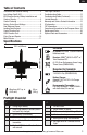
EN Table of Contents Transmitter and Receiver Binding...........................4 Low Voltage Cutoff (LVC)........................................4 ESC/Receiver Arming, Battery Installation and Center of Gravity....................................................5 Control Centering ..................................................6 Factory Control Horn Settings................................6 Dual Rates and Expos............................................6 Landing Gear Removal...........................
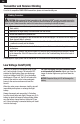
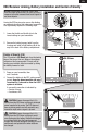
EN Transmitter and Receiver Binding For a list of compatible DSM2/DSMX transmitters, please visit www.bindnfly.com Binding Procedure CAUTION: When using a Futaba transmitter with a Spektrum DSM® module, you must reverse the throttle channel and rebind. Refer to your Spektrum module manual for binding and failsafe instructions. Refer to your Futaba transmitter manual for instructions on reversing the throttle channel. 1.
EN ESC/Receiver Arming, Battery Installation and Center of Gravity NOTICE: Always keep material or debris away from the intake. When armed, the rotor will turn in response to throttle movement and could ingest in any loose objects. 1 Arming the ESC/receiver also occurs after binding as previously described, but subsequent connection of a flight battery requires the following steps. 1. Lower the throttle and throttle trim to the lowest settings on your transmitter. 2 A 2.
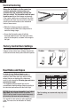
EN Control Centering Before the first flights, or in the event of an accident, make sure control surfaces are centered when the transmitter controls and trims are neutral. The transmitter sub-trim must be set to zero. Adjust the linkages mechanically if the control surfaces are not centered. Use of the transmitter sub-trims may not correctly center the aircraft control surfaces due to the mechanical limits of linear servos. • Make the U-shape narrower to make the connector shorter.
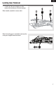
EN Landing Gear Removal 1. Carefully pull the gear straight out of the retainer clip that secures it into the fuselage. When needed, assemble in reverse order. When the landing gear is reinstalled, make sure the nose gear is angled forward as shown.
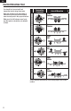
EN Control Direction Test Make sure the tail linkages move freely and that paint or decals are not adhered to them. Transmitter Command Aircraft Reaction Down Elevator Elevator You should bind your aircraft and transmitter before doing these tests. Move the controls on the transmitter to make sure the aircraft control surfaces move correctly and in the proper direction.
EN AS3X Direction Test You should bind your aircraft and transmitter before doing these tests. Move the controls on the transmitter to make sure the aircraft control surfaces move correctly and in the proper direction. Make sure the tail linkages move freely and that paint or decals are not adhered to them. Aircraft movement AS3X Reaction Arrows indicate the direction of the trailing edge of the control surface.
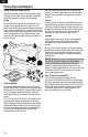
EN Flying Tips and Repairs Range Check your Radio System After final assembly, range check the radio system with the aircraft. Refer to your specific transmitter instruction manual for range test information. Flying We recommend flying your aircraft outside in no greater than moderate winds or inside in a very large indoor facility. Always avoid flying near houses, trees, wires and buildings. Be careful to avoid flying in areas where there are many people, such as busy parks, schoolyards or soccer fields.
EN Motor Service Disassembly CAUTION: DO NOT handle the rotor or motor while the flight battery is connected. Personal injury could result. 1. The lower half of the nacelle hatch is secured to the top half using glue and clear tape. Carefully cut the clear tape and follow the seam with a knife to cut the glue and remove the bottom half of the nacelle. NOTICE: Removing tape or decals can damage paint on your aircraft. Avoid pinching or otherwise damaging any wires when opening or closing the fuselage.
EN Post Flight Checklist 1. Disconnect the flight battery from the ESC (Required for safety and battery life). 5. Store the flight battery apart from the aircraft and monitor the battery charge. 2. Power OFF the transmitter. 6. Make note of the flight conditions and flight plan results, planning for future flights. 3. Remove the flight battery from the aircraft. 4. Recharge the flight battery.
EN Troubleshooting Guide (Continued) Problem Possible Cause Solution LED on receiver flashes Less than a 5-second wait between first rapidly and aircraft will powering on transmitter and connecting not respond to transmit- flight battery to aircraft ter (after binding) Aircraft bound to different model memory (ModelMatch™ radios only) Control surface does not move Leaving transmitter on, disconnect and reconnect flight battery to aircraft Select correct model memory on transmitter and disconnect and r
EN Horizon reserves the right to inspect any and all Product(s) involved in a warranty claim. Service or replacement decisions are at the sole discretion of Horizon. Proof of purchase is required for all warranty claims. SERVICE OR REPLACEMENT AS PROVIDED UNDER THIS WARRANTY IS THE PURCHASER’S SOLE AND EXCLUSIVE REMEDY.
EN Warranty and Service Contact Information Country of Purchase United States of America Horizon Hobby Phone Number/Email Address Horizon Service Center (Repairs and Repair Requests) servicecenter.horizonhobby. com/RequestForm/ productsupport@ horizonhobby.
EN Compliance Information for the European Union EFL UMX A-10 BNF Basic (EFLU3750) EU Compliance Statement: Horizon Hobby, LLC hereby declares that this product is in compliance with the essential requirements and other relevant provisions of the RED Directive. A copy of the EU Declaration of Conformity is available online at: http://www.horizonhobby.com/ content/support-render-compliance.
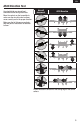
Replacement Parts – Ersatzteile – Pièces de rechange – Ricambi Part # • Nummer Numéro • Codice Description Beschreibung Description Descrizione EFLAS6410NBLT DSMX 6-Ch AS3X receiver w/Twin Brushless ESC DSMX 6-Kanal AS3X Empfänger mit bürstenlosem doppeltem Geschwindigkeitsregler Récepteur DSMX 6 voies AS3X avec double contrôleur Brushless Ricevente AS3X a 6 canali DSMX con doppio ESC brushless EFLDF180M1 Rotor: Delta-V 180m Rotor: Delta-V 180 m Delta-V 180m Rotor pour turbine Rotore: Delta-V
– Optional Parts and Accessories – – Optionale Bauteile und Zubehörteile – – Pièces optionnelles et accessoires – – Parti opzionali e accessori – Part # • Nummer Description Numéro • Codice Beschreibung Description Descrizione EFLA230 Charger Lead with JST Female E-flite Ladekabel m/ JST Buchse Câble de charge avec prise JST femelle Cavo di carica con femmina JST DYNC2010CA Prophet Sport Plus 50W AC/DC Charger Prophet Sport Plus 50 W Wechsel-/ GleichstromLadegerät Chargeur Prophet Sport Plus 50W
© 2016 Horizon Hobby, LLC. E-flite, AS3X, UMX, DSM, DSM2, DSMX, ModelMatch, Bind-N-Fly, Celectra and the Horizon Hobby logo are trademarks or registered trademarks of Horizon Hobby, LLC. The Spektrum trademark is used with permission of Bachmann Industries, Inc. Futaba is a registered trademark of Futaba Denshi Kogyo Kabushiki Kaisha Corporation of Japan. All other trademarks, service marks and logos are property of their respective owners. US 7,898,130. US D578,146. PRC ZL 200720069025.