
UMX Turbo Timber BNF Basic - Manual

8
EN
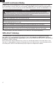
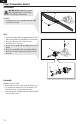
Control Centering
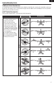
Control Horn Settings
The illustration shows linkage positions chosen for the best
aerobatic response. Linkage connections on the control
horns directly affect aircraft response.
Aileron
RudderElevator
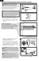
Before your first flight, make sure the aircraft’s control
surfaces are centered.
1. Power on the transmitter and then the aircraft.
2. Set all transmitter trims and sub-trims to zero.
3. Check the control surfaces to make sure they are
centered.
4. If centering is required, use a pair of pliers to carefully
bend the metal linkage (see illustration).
In flight trimming may be required.
During your first flight, the aircraft should fly straight and
level. Use your transmitter trims to fine-tune the aircraft’s
flight path until it has been corrected. Any transmitter trim
that requires 4 or more clicks of trim (per channel), should
be mechanically centered. Note the control surface’s
postion and return the transmitter trim to zero. Adjust the
linkages mechanically so that the control surfaces are in
the flight trimmed position.
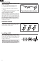
Make the U-shape narrower to make the connector shorter.
Make the U-shape wider to make the linkage longer.
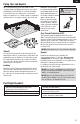
LVC is a feature built into your ESC to protect the battery
from over-discharge. When the battery charge becomes too
low, LVC limits power supplied to the motor. When you hear
the motor power pulse, land the aircraft immediately and
recharge the flight battery.
NOTICE: Do not rely on LVC to determine when to land
your aircraft. Set a flight timer to the recommended flight
time. Repeated flying to LVC will damage the battery.
Low Voltage CutOff