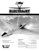
TM TM INSTRUCTION MANUAL • Assembly time 3–5 hours • Foam construction • Stable, sporty flight characteristics Specifications Wingspan: . . . . . . . . . . . . . . . . . . . . . 33.25" (844.6 mm) Overall Length. . . . . . . . . . . . . . . . . . . . 29" (736.6 mm) Ready-To-Fly Weight. . . . . . . . 16–24 oz (436.6–680.4 g) Radio (not included) . . . . . . . . . . . . 3-channel minimum Battery Pack (not included) . . . . . . . . . . . . . . . . . . . . . . . . . . . . . . . . . . . . .
Table of Contents Introduction . . . . . . . . . . . . . . . . . . . . . . . . . . . . . . . . . . . . 2 Assembly Tips . . . . . . . . . . . . . . . . . . . . . . . . . . . . . . . . . . . 2 Kit Contents . . . . . . . . . . . . . . . . . . . . . . . . . . . . . . . . . . . . 3 Required Additional Equipment . . . . . . . . . . . . . . . . . . . . . . 3 Assembling the Main Wing and Servos . . . . . . . . . . . . . . . . 4 Installing the Motor Mount . . . . . . . . . . . . . . . . . . . . . . . . .
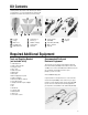
Kit Contents Carefully examine the contents of this kit before you start the assembly process. It is recommended that you carefully read through this instruction manual before you start assembly.
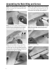
Assembling the Main Wing and Servos Step 1. Use a sanding block with fine sandpaper (preferably 400 grit) to remove the flashing from the areas that glue will be applied on all foam parts. (Please read ahead to find out where glue will be applied.) Step 2. Trial fit the wings (both the left and right panel) onto the fuselage. When you are satisfied with the fit, mix an adequate amount of 12-minute epoxy and apply the epoxy to the wing joiner slots (located on the fuselage) onto the main wings. Step 3.
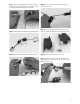
Step 7. Please locate the indentations made on the elevons for the control horns. Install the control horns to the elevons using 12-minute epoxy. Allow the epoxy to cure completely. Step 10. Use a 2.0-mm drill bit to open up the holes in the servo arm of each servo. Step 8. Locate two micro servos and two sets of pushrod connectors. Step 11. Insert the pushrod connectors into the holes in the servo arms, but do not tighten the servo arm down at this time. Step 9.
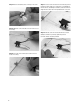
Step 14. Remove the backing of the servo tape on the servos. Step 17. Insert the other end of the Z-bent rod into the pushrod connector. It will be helpful to use small pieces of masking tape to hold the ailerons at the 0-degree deflection (centered on airfoil of wing) while the control rods are being attached to the servo arms. Step 15. Mount the servos and cables into each of the recesses in the wings. Step 18.
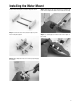
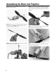
Installing the Motor Mount Locate all motor mount parts as located in the picture below. Step 1. Assemble the motor mount, but do not glue any of the motor mount parts together! Step 3. Apply epoxy to the motor mount recesses located in the center of the fuselage and install the motor mount to the fuselage. Step 4. Use masking tape to hold the motor mount in place on the fuselage. Step 2. Mix an adequate amount of 12-minute epoxy and apply to the dowels.
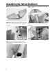
Assembling the Vertical Stabilizers Step 1. Locate the two vertical stabilizers. Step 2. Mix an adequate amount of 12-minute epoxy and apply to the recesses on the fuselage where the vertical stabilizers will be mounted. Step 3. Use a pin to hold the vertical stabilizers in place. (Masking tape can also be used, but remember it can mark the surface of the foam). 8 Step 4. The distance between the leading edge of the vertical stabilizers is 215 mm. Step 5.
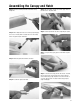
Assembling the Canopy and Hatch Step 1. Remove the flashing around the hatch with a sharp hobby knife. Step 2. Mix an adequate amount of 12-minute epoxy and apply to the recess in hatch (which is located at the rear of the hatch) and to one plywood square hold-down. Step 5. Mix an adequate amount of 12-minute epoxy and coat the underside on the plastic latch. Step 6. Place the plastic latch onto the fuselage and glue in place. Step 7. Using 12-minute epoxy, glue the hatch-latch recepticle in place.
Assembling the Motor and Propeller Step 1. Locate the spinner, aluminum nut, set screw, and propeller from the kit contents. Step 2. When you insert the nut into the propeller, the printing on the 8"x4" propeller must face toward the gearbox of the motor when it is mounted to the motor. Step 3. Use a propeller wrench to secure the spinner, aluminum nut, and propeller to the propeller shaft. 10 Step 4. Use the 1.
Installing the Speed Controller and Delta Mixer Step 1. Glue the Velcro® strip to one side of the fuselage. This will be used to secure the battery in the fuselage. Step 4. Pass the delta mixer wires out through the fuselage onto the wing, as shown in the picture below. Step 2. Locate the receiver, speed controller and delta mixer. Please refer to the instructions provided with the speed controller and delta mixer for an outline of the installation steps and drawings of wiring and hook-up schematics.
Assembling the Tail Fin and Servo Connectors Step 1. Make sure the power switch is off and that the battery is not connected before you connect the motor and speed control plug. Warning: Always assume the motor can come on at any time. Be absolutely certain no power is connected to the motor while you are working around it. Step 5. Fix the servo wires to the wing with the 10 mm sticker tape provided Step 2. Now is the time to install the bottom vertical fin with odorless CA, as shown in the picture below.
Battery Charger Refer to the instruction sheet provided with the charger. CAUTION It is important you read the instructions for proper operation of the charger before you attempt charging the battery. Failure to do so could result in injury or damage to property. Prior to First Flight Step 1. Ensure that all electronic and radio equipment is properly installed and connected and that the battery is charged. Step 4. Check for proper movement of the elevons and speed controller.
AMA Safety Code 2001 Official AMA National Model Aircraft Safety Code Effective January 1, 2001 Model flying must be in accordance with this code in order for AMA liability protection to apply. General 1. I will not fly my model aircraft in sanctioned events, air shows, or model flying demonstrations until it has been proven to be airworthy by having been previously, successfully flight tested. 2.
ElectraJet™ Spare Parts List • Wing Replacement (EFL1001) • Fuselage Replacement (EFL1002) • Tail Replacement (EFL1003) • Hardware Kit (EFL1004) • Speed Controller (EFLA100) • Delta Mixer (EFLA101) • Propeller (EFLA300) • Power Unit (EFLA400) Glossary of Terms Activating (Arming) Switch: An external switch that prevents the electric motor from accidentally turning on. Axis: A line passing through a body about which the body revolves.
© Copyright 2001, Horizon Hobby, Inc. www.horizonhobby.