FJ–2 Fury 15 DF Instruction Manual / Bedienungsanleitung Manuel d’utilisation / Manuale di Istruzioni
EN NOTICE All instructions, warranties and other collateral documents are subject to change at the sole discretion of Horizon Hobby, LLC. For up-to-date product literature, visit www.horizonhobby.com and click on the support tab for this product.
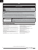
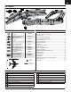
EN Box Contents Specifications Ducted Fan Unit: EDF Fan Unit (EFL725013) Motor: BL15 Ducted Fan Motor, 3700Kv (EFLM3315DF) ESC: 60-Amp Brushless ESC (EFL725017) Table of Contents Installed Installed Installed (6) Servos Installed Receiver: Spektrum™ AR636 6-Channel Sport Receiver Installed Battery: 3200mAh 14.8V 4-cell 30C Li-Po (EFLB32004S30) Battery Charger: Prophet™ Sport Plus 50W AC DC Charger (DYNC2010CA) Recommended Transmitter: Full-Range 2.
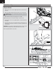
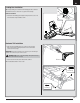
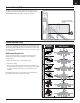
EN Model Assembly Wing Installation 1. Guide the aileron servo connectors (A) through the hole located to the side of fan unit. B 2. Slide the two guide pins (B) of the wing into the two holes in the fuselage. CAUTION: DO NOT crush or otherwise damage wiring when attaching the wing to the fuselage. 3. Align and attach the wing to the fuselage using a screw (C). Tip: Carefully support the aircraft while installing or removing screws. 4.
EN Landing Gear Installation Tip: For belly landing, do not install the main landing gear and see the Nose Gear Removal section to remove the nose gear from the fuselage. A Main Gear Installation 1. Install each main landing gear strut (A) in a wing mount. The coils on the struts should be facing rearward as shown. Horizontal Tail Installation 1.
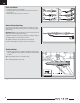
EN Clevis Installation • Pull the tube from the clevis to the linkage. • Carefully spread the clevis, then insert the clevis pin into the outer hole in the control horn. • Move the tube to hold the clevis on the control horn. 1. 4. 2. 5. 3. 6. Control Surface Centering After assembly, confirm that the control surfaces are centered. If the control surfaces are not centered, mechanically center the control surfaces by adjusting the linkages.
EN Control Horn and Servo Arm Settings The table to the right shows the factory settings for the control horns and servo arms. Fly the aircraft at factory settings before making changes. Horns Arms Elevator Rudder Ailerons Transmitter Setup IMPORTANT: Set up your transmitter before binding your transmitter to the aircraft. Transmitters DX6i and Above Start all transmitter programming with a blank ACRO model (do a model reset), then name the model. Leave all settings at default.
EN Transmitter and Receiver Binding Binding Procedure IMPORTANT: The included AR636 receiver has been programmed for operation in only this aircraft. Refer to the receiver manual for correct setup if the receiver is replaced or is used in another aircraft. Read the transmitter instructions for binding to a receiver (location of transmitter’s Bind control). Please visit www.bindnfly.com for a complete list of compatible transmitters.
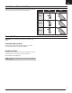
EN Center of Gravity (CG) The CG location is measured from the leading edge of the wing at the root. This CG location has been determined with the recommended Li-Po battery (EFLB32004S30) installed in the middle of the battery compartment. 6.1 inches back from the leading edge of the wing at the root. 155mm Control Direction Tests AS3X Control Direction Test This test ensures that the AS3X® control system is functioning properly.
EN Flying Tips and Repairs Consult local laws and ordinances before choosing a flying location. Range Check your Radio System Before you fly, range check the radio system. Refer to your specific transmitter instruction manual for range test information. Oscillation Once the AS3X system is active (after advancing the throttle for the first time), you will normally see the control surfaces react to aircraft movement.
EN Post Flight 1 Disconnect the flight battery from the ESC (Required for Safety and battery life). 5 Repair or replace all damaged parts. 2 Power OFF the transmitter. 6 Store the flight battery apart from the aircraft and monitor the battery charge. 3 Remove the flight battery from the aircraft. 7 4 Recharge the flight battery. Make note of the flight conditions and flight plan results, planning for future flights.
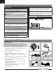
EN Nose Gear Removal A Tip: For belly landing, remove the nose gear from the fuselage. 1. Remove the 6 screws (A) and the nose cover (B) from the fuselage. 2. Loosen the set screw (C) in the steering arm (D) using a hex wrench, then remove the arm from the nose strut (E). B 3. Remove the nose strut from the cover. 4. Disconnect the nose gear linkage (F) from the innermost hole in the steering servo arm (G). 5. Disconnect the steering servo from the servo extension in the fuselage.
EN Troubleshooting Guide Problem Possible Cause Solution Incorrect response to the AS3X Control Direction Test Incorrect direction settings in the receiver, which can cause a crash DO NOT fly.
EN AMA National Model Aircraft Safety Code Effective January 1, 2014 A. GENERAL A model aircraft is a non-human-carrying aircraft capable of sustained flight in the atmosphere. It may not exceed limitations of this code and is intended exclusively for sport, recreation, education and/or competition. All model flights must be conducted in accordance with this safety code and any additional rules specific to the flying site. 1. Model aircraft will not be flown: (a) In a careless or reckless manner.
EN Limited Warranty What this Warranty Covers Horizon Hobby, LLC, (Horizon) warrants to the original purchaser that the product purchased (the “Product”) will be free from defects in materials and workmanship at the date of purchase.
EN Contact Information Country of Purchase Horizon Hobby Horizon Service Center (Repairs and Repair Requests) United States of America Horizon Product Support (Product Technical Assistance) Sales United Kingdom Germany France China Service/Parts/Sales: Horizon Hobby Limited Horizon Technischer Service Sales: Horizon Hobby GmbH Service/Parts/Sales: Horizon Hobby SAS Service/Parts/Sales: Horizon Hobby – China Phone Number/Email Address servicecenter.horizonhobby.com/ RequestForm/ www.quickbase.
Replacement Parts • Ersatzteile • Pièces de rechange • Pezzi di ricambio Part # | Nummer Numéro | Codice Description Beschreibung EFL725001 Fuselage w/o hatch: Fury 15 DF E-flite Fury 15: Rumpf ohne Haube EFL725002 EFL725004 Wing: Fury 15 DF Stabilizer: Fury 15 DF E-flite Fury 15: Tragfläche E-flite Fury 15: Leitwerk EFL725005 Fin w/ Rudder: Fury 15 DF E-flite Fury 15: Finne mit Ruder EFL725006 EFL725009 Fuse Hatch: Fury DF 15 Landing Gear Set: Fury 15 DF Canopy: Fury 15 DF Screw Set: Fury 15 DF E
© 2014 Horizon Hobby, LLC. E-flite, AS3X, Delta-V, EC3, Prophet, DSM, DSM2, DSMX, the DSMX logo, Z-Foam, Bind-N-Fly, the BNF logo, and ModelMatch are trademarks or registered trademarks of Horizon Hobby, LLC. The Spektrum trademark is used with permission of Bachmann Industries, Inc. Futaba is a registered trademark of Futaba Denshi Kogyo Kabushiki Kaisha Corporation of Japan. All other trademarks, service marks and logos are property of their respective owners. Patents pending. http://www.e-fliterc.