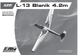
ARF ALMOST-READY-TO-FLY L-13 Blanik 4.2m Instruction Manual Bedienungsanleitung Manuel d’utilisation Manuale di Istruzioni The Red Bull name and likeness is used under license of Red Bull GmbH Austria.
NOTICE All instructions, warranties and other collateral documents are subject to change at the sole discretion of Horizon Hobby, Inc. For up-to-date product literature, visit horizonhobby. com and click on the support tab for this product. Meaning of Special Language HINWEIS Alle Anweisungen, Garantien und anderen zugehörigen Dokumente können im eigenen Ermessen von Horizon Hobby, Inc. jederzeit geändert werden. Die aktuelle Produktliteratur finden Sie auf horizonhobby.
REMARQUE La totalité des instructions, garanties et autres documents est sujette à modification à la seule discrétion d’Horizon Hobby, Inc. Pour obtenir la documentation à jour, rendez-vous sur le site horizonhobby.com et cliquez sur l’onglet de support de ce produit. Signification de certains termes spécifiques AVVISO Tutte le istruzioni, le garanzie e gli altri documenti pertinenti sono soggetti a cambiamenti a totale discrezione di Horizon Hobby, Inc.
SAFETY WARNINGS AND PRECAUTIONS WARNUNGEN UND SICHERHEITSVORKEHRUNGEN AVERTISSEMENTS RELATIFS À LA SÉCURITÉ AVVERTIMENTI E PRECAUZIONI PER LA SICUREZZA Read and follow all instructions and safety precautions before use. Improper use can result in fire, serious injury and damage to property. Bitte lesen und befolgen Sie alle Anweisungen und Sichervorkehrungen vor dem Gebrauch. Falscher, nicht sachgemäßer Gebrauch kann Feuer, ernsthafte Verletzungen und Sachbeschädigungen zur Folge haben.
SAFE OPERATING RECOMMENDATIONS EMPFEHLUNGEN ZUM SICHEREN BETRIEB CONSIGNES DE SÉCURITÉ CONCERNANT L’UTILISATION RACCOMANDAZIONI PER OPERARE IN SICUREZZA • Inspect your model before every flight to ensure it is airworthy. • Überprüfen Sie zur Flugtauglichkeit ihr Modell vor jedem Flug. • Inspectez votre modèle avant chaque vol. • Controllare attentamente il modello prima di ogni volo per accertarsi che sia idoneo. • Be aware of any other radio frequency user who may present an interference problem.
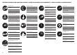
ASSEMBLY SYMBOL GUIDE/MONTAGE SYMBOLE /GUIDE DES SYMBOLES POUR ASSEMBLÉE /GUIDA AI SIMBOLI DI ASSEMBLAGGIO Apply threadlock Ensure free rotation Use medium CA Use a pencil Schraubensicherungslack verwenden Rotation sicherstellen Mittelflüssigen Sekundenkleber verwenden Verwenden Sie einen Bleistift Permettez une rotation libre Utilisez du frein filet Utilisez de la cyanoacrylate moyenne Assicurarsi rotazione libera Applicare fuido threadlock Utilisez un crayon à papier Usare una matita Usare CA
T hank you for purchasing this 1/4-scale model of the Red Bull sponsored aerobatic Blanik sailplane. With its unique forward swept wings and upswept horizontal stabilizer, the E-flite® Blanik sailplane offers a distinct, unmistakable presence in flight. The full sized Blanik is an airshow sensation and this model is no different. Perfectly suited for aerotowing or slope soaring, the Blanik is an aerobatic force to reckon with.
FASTENERS/VERBINDUNGSELEMENTE/LIAISONS/ELEMENTI DI FISSAGGIO M3 x 10 mm self-tapping screw (6) M3 x 10mm selbstschneidene Schraube(6) Vis auto-taraudeuse M3x10mm (6) M3 x 10 mm vite autofilettante (6) M3 x 10 mm flat socket head (6) M3 x 10 Senkkopfschraube (6) Vis à tête fraisée M3x10mm (6) M3 x 10 mm a testa piatta (6) M2 x 8 mm self-tapping screw (16) M 2 x8 mm selbstschneidene Schraube (16) Vis auto-taraudeuse M2x8mm (16) M2 x 8 mm vite autofilettante (16) M2 x 20 mm screw (1) M2 x 20 Inbusschraube (1)
Qty Part English Deutsch Français Italiano 1 SPMA3008 Heavy-Duty Y-Harness, 6-inch Spektrum Hochleistungs Y- Servokabel Cordon Y longueur 15 cm Prolunga a Y da 15cm per carichi pesanti 1 SPM9530 Spektrum™ 3-Wire Switch Harness Spektrum Schalterkabel 3 Anschlüsse Interrupteur Spektrum à 3 fils Interruttore Spektrum 3 fili 1 JRPB4550 Extra Receiver Pack 3000mAh 6V Ni-Cd Flat Empfängerakku 3000mAh 6 Volt Flach Batterie de réception Ni-Cd 6V 3000mA Batteria piatta extra da 3000mAh 6V 1 DUB
BEFORE STARTING ASSEMBLY VOR DEM ZUSAMMENBAU • Remove parts from bag. • Entnehmen Sie zur Überprüfung jedes Teil der Verpackung. • Inspect fuselage, wing panels, rudder and stabilizer for damage. • If you find damaged or missing parts, contact your place of purchase. If you find any wrinkles in the covering, use a heat gun (HAN100) and covering glove (HAN150) or covering iron (HAN101) with a sealing iron sock (HAN141) to remove them.
WING ASSEMBLY/ 1 2 Use low-tack tape to prevent epoxy from getting on the aileron and flap surfaces. Lightly sand the control horn where it enters the control surface. ZUSAMMENBAU DER TRAGFLÄCHEN/ ASSEMBLAGE DE L’AILE/ MONTAGGIO DELL’ALA/ Verwenden Sie Klebeband mit geringer Klebekraft um zu verhindern, dass Epoxy auf die Klappen und Querruder kommt. Utilisez de l’adhésif de masquage pour éviter de faire couler de la colle epoxy sur la surface des ailerons et des volets.
3 4 5 Aileron/ Querruder/ Ailerons/ Alettone/ Flap/ Klappen/ Volets/ Flap Remove the tape before the epoxy fully cures. Entfernen Sie das Klebeband bevor der Kleber getrocknet ist. Retirez l’adhésif de masquage avant le séchage de la colle. Togliere il nastro adesivo prima che la colla si indurisca completamente. 30 x4 Apply a small amount of epoxy in the slot and to the control horn. Geben Sie eine kleine Menge Epoxy in die Öffnung und auf das Ruderhorn.
6 7 Aileron/ Querruder/ Ailerons/ Alettone/ 8 Front of the wing/ Vorderseite der Tragfläche/ Bord d’attaque de l’aile/ Bordo di entrata ala 3 mm 3 mm Flap/ Klappen/ Volets/ Flap 4 mm x4 4 mm Front of the wing/ Vorderseite der Tragfläche/ Bord d’attaque de l’aile/ Bordo di entrata ala LL RR Align the servos on the aileron and flap servo doors as shown. Pay attention to prepare a left and right side. Richten Sie die Servos auf den Abdeckungen wie abgebildet aus.
9 10 11 20mm 20mm 17mm Aileron/Querruder/ Ailerons/Alettone 30 Use a pin vise with a 1/16” (1.5mm) drill bit to drill holes for the servo screws. Bohren Sie mit einem 1,5mm Handbohrer die Löcher für die Servobefestigungsschrauben. Utilisez un porte-foret et un foret de 1.5mm pour pré-percer les trous de fixation des servos. Praticare i fori per le viti dei servi con una punta da 1,5mm x4 Mount the servos to the blocks using a #1 screw driver. Glue the blocks to the doors with 30 minute epoxy.
12 x2 Connect the 48” servo extension to the aileron servo lead and shrink a 1 1/2” piece of 3/8” shrink tubing over the connection. Schließen Sie die 48” (121,92cm) Servoverlängerung an das Querruderservo an und schrumpfen die Steckerverbindung mit einem 4 cm langen Stück 9,5mm breiten Schrumpfschlauch ein. Connectez une rallonge de 120 cm à chaque prise de servo d’aileron et placez un morceau de gaine thermo-rétractable de 4cm de long pour sécuriser la connexion.
OPTIONAL SPOILER INSTALLATION/ 1 2 EINBAU DER OPTIONALEN STÖRKLAPPEN/ INSTALLATION DES AÉROFREINS OPTIONNELS/ INSTALLAZIONE AEROFRENI OPZIONALI/ IMPORTANT: If you are installing the optional E-flite® retractable spoilers (EFL491009), use a receiver with 8 or more channels. At least 8 channels are required for correct operation. WICHTIG: Wenn Sie die optionalen E-flite Störklappen (EFL491009) einbauen benötigen Sie mindestens einen Empfänger mit 8 Kanälen.
3 4 5 x2 Connect the spoiler to a servo driver or your radio system and fully open the spoiler. Schließen Sie die Störklappe an einen Servoanschluß des Empfängers ihrer Fernsteuerung an und fahren die Klappe vollständig aus. Connectez l’aérofrein à la rallonge de servo et déployez-le entièrement. Collegare l’aerofreno ad un provaservi o al radiocomando per aprirlo completamente. x2 x2 Connect an 18” extension to the spoiler lead, then shrink a 1 1/2” piece of 3/8” shrink tubing over the connection.
6 7 8 x2 x2 5 Mount the spoiler to the channel in the wing using a #1 screwdriver. Thread the three included self-tapping screws into the pre-drilled holes. Setzen Sie die Störklappe mit einem #1 Schraubendreher in die Tragfläche ein und drehen die drei selbstschneidenen Schrauben in die vorgebohrten Löcher. Fixez l’aérofrein dans son emplacement en utilisant 3 vis autotaraudeuses et un tournevis cruciforme #1. Fissare l’aerofreno all’ala usando un cacciavite #1.
FLAP INSTALLATION/ 1 2 x2 x2 EINBAU DER LANDEKLAPPEN/ INSTALLATION DES VOLETS/ INSTALLAZIONE FLAP/ Connect the 18” servo extension to the flap servo lead, then shrink a 1 1/2” piece of 3/8” shrink tubing over the connection. Tie the string located inside the wing around the end of the extension. Pull the lead through the wing. Schließen Sie die 45,72cm lange Verlängerung an das Servoklappenkabel an und sichern die Verbindung mit einem 4 cm langen Stück 9,5mm breiten Schrumpfschlauch.
3 4 5 Flap/ Klappen/ Volets/ Flaps/ Aileron/ Querruder/ Ailerons/ Alettoni/ 63 mm 100 mm Place the flap linkage into the slot in the wing. Connect the clevis to the flap control horn. Setzen Sie die Klappenanlenkung in die Tragfläche ein. Schließen Sie den Gabelkopf am Klappenruderhorn an. Placez la tringlerie de volet dans la fente de l’aile. Emboîtez la chape dans le bras du servo de volet. Inserire la barretta di comando del flap nella fessura dell’ala. Collegare la forcella alla squadretta del flap.
6 WINGTIP INSTALLATION/ 1 MONTAGE DER TRAGFLÄCHENSPITZEN/ INSTALLATION DES SAUMONS D’AILES/ INSTALLAZIONE TERMINALI ALARI Connect the aileron linkage to the servo arm and control horn. Schließen Sie die Queruderanlenkung am Servo- und Ruderhorn an. x2 Connectez la tringlerie d’ailerons entre le bras du servo et le guignol. Sand the mating surface of the wingtip to provide good adhesion. Collegare la barretta di comando alla squadretta della superficie mobile e a quella del servo.
2 3 4 x2 x2 x2 Apply 5-minute epoxy to the mating surface. Geben Sie 5 Minuten Epoxy auf die angeschliffene Innenseite der Tragflächenspitzen. Appliquez de la colle époxy 5 minutes sur la surface de contact. Spalmare della colla epoxy 5 minuti sulla superficie di contatto. Before the epoxy cures, use rubbing alcohol and a paper towel to remove any excess. Entfernen Sie überschüssigen Klebstoff mit Alkohol und einem Papiertuch bevor der Kleber getrocknet ist.
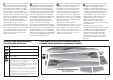
LANDING GEAR INSTALLATION/ 1 2 EINBAU DES FAHRWERKS/ INSTALLATION DU TRAIN D’ATTERRISSAGE/ INSTALLAZIONE CARRELLO/ x2 Mount the two upper mounting plates to one of the wheel supports using the included counter sunk machine screws and a 2 mm hex driver. Use threadlock on all screws. Ensure the counter sunk screw holes face out. Schrauben Sie mit den Senkkopfschrauben und einem 2mm Inbusschlüssel die beiden Haltestreben an die Seitenplatte.
3 4 5 Front/ Vorne/ Avant/ Davanti/ Install the wheel assembly into the fuselage with the taller vertical section to the front as shown in the above diagram. Mount the remaining wheel support plate. Schrauben Sie die zweite Halteplatte an. Montez la deuxième platine. Montare l’altro supporto per la ruota. Setzen Sie den Radträger mit der größeren Seite nach vorne zeigend wie abgebildet in den Rumpf ein.
6 TAIL SURFACE HINGING/ 1 MONTAGE DER LEITWERKE UND RUDER/ INSTALLATION DES CHARNIÈRES DE L’EMPENNAGE/ INCERNIERARE LA SUPERFICIE DI CODA/ Install the tail wheel into the slot on the bottom of the fuselage. Secure the wheel using the included M2 X 20 mm screw and lock nut. Setzen Sie das Spornrad in die Radöffnung ein und sichern Sie es mit dem im Lieferumfang enthaltenen M2 x 20 Schrauben und Stopmuttern. Installez la roulette de queue dans son emplacement situé sous le fuselage.
2 3 4 30 Apply 30-minute epoxy to the hinges mounted in the rudder and the holes in the vertical stabilizer. Install the rudder hinges into the holes in the stabilizer and use rubbing alcohol and a paper towel to remove any excess epoxy before it cures. Geben Sie 30 Minuten Epoxy auf die Scharniere des Seitenruders und in die Löcher des Höhenruders. Setzen Sie die Scharniere in die Löcher im Höhenruder und entfernen überschüssigen Klebstoff mit einem Papiertuch und Reinigungsalkohol bevor er trocknet.
6 7 8 Test fit the servo in the stabilizer half. Confirm the spacing of the control horn with the pre-cut slot in the stabilizer surface. Use lite-ply spacers as necessary to align the servo so the servo arm will be centered in the slot. Mark the screw locations with a felt tipped pen. Prüfen Sie die Passung des Servos im Höhenruder und die Positionierung des vorgefertigten Schlitzes in der Ruderfläche.
9 10 11 Repeat steps 6–10 to assemble the other horizontal stabilizer half. Wiederholen Sie die Schritte 6–10 um die zweite Höhenruderhälfte zu montieren. Répétez les étapes de 6 à 10 pour assembler le deuxième demi-stab. Ripetere i passi da 6 a 10 per montare l’altra metà dello stabilizzatore orizzontale. 14 mm 14 mm 66 mm LL RR Assemble the linkage and connect the clevises to the servo arm and control horn. Install the servo using the self-tapping screws included with the servo.
ELEVATOR INSTALLATION/ 1 2 EINBAU DES HÖHENLEITWERKS/ INSTALLATION DU STABILISATEUR/ INSTALLAZIONE DELL’ELEVATORE/ Insert the carbon rods for mounting the horizontal stabilizer into one stabilizer half. Stecken Sie die Carbonstäbe in eine Höhenleitwerkshälfte Insérez les clés en carbone dans un des demi-stabilisateurs.
3 4 5 Tie a washer or other weight to one end of a piece of string. Hold the fuselage vertical (nose down), and feed the weight through the front-most hole where the horizontal stabilizer mounts. Allow the weight to pull the string through the fuselage. Tie the end of the string around the extension connected to the elevator servo. Pull the extension through the fuselage and install the stabilizer half into the fuse. Use clear electrical tape to secure the stabilizer to the fuselage.
VERTICAL STABILIZER INSTALLATION/ 1 2 EINBAU DES SEITENLEITWERKS/ INSTALLATION DE LA DÉRIVE/ INSTALLAZIONE IMPENNAGGIO VERTICALE/ Sand the mating surface of the vertical stabilizer and fuselage for good adhesion Schleifen Sie die Klebefläche des Seitenleitwerks am Rumpf für eine saubere Verklebung an. Poncez la surface de contact de la dérive pour assurer une bonne adhérence. Per avere una buona aderenza, carteggiare la superficie del direzionale che va ad appoggiarsi sulla fusoliera.
3 30 Apply 30-minute epoxy to the carbon rods mounted in the vertical stabilizer and the fuselage where the vertical stabilizer will be mounted. Geben Sie 30 Minuten Epoxy auf die Carbonstangen die im Seitenleitwerk montiert sind und auf den Leitwerksträger am Rumpf. Appliquez de l’époxy 30 minutes sur les tubes carbone qui sont insérés dans la dérive et sur le fuselage au niveau de la jonction dérive/fuselage. Mettere della colla epoxy 30 minuti sulla baionetta già inserita nell’impennaggio verticale.
PULL-PULL CABLE PREPARATION/ 1 2 Pull the cable through the crimp sleeve and the threaded cable end. Feed the cable through the sleeve. Loop the cable back around and through the sleeve. Pull the loop taut with minimal overhang. Führen Sie das Kabel durch die Quetschhülse und durch den Augenbolzen, danach wieder durch die Hülse. Führen Sie das Kabel mit einer Schlaufe durch die Quetschhülse. Ziehen Sie das Kabel mit minimalen Überhang stramm. Glissez le câble dans le tube laiton et dans l’oeillet.
3 4 5 Carefully crimp the sleeve with side cutters. Trim any excess cable end. Enlarge the openings in the fuselage as necessary to allow the cable end and sleeve to fit. Hold the fuselage vertical (nose down). Insert the threaded cable end into the opening. Allow the cable end to pull the cable through. Tip the fuselage as necessary so the cable goes through the upper opening of the rear bulkhead and through the lower opening in the middle bulkhead.
6 RUDDER SERVO INSTALLATION/ Repeat steps 1–5 to assemble the cable for the opposite side. EINBAU DES SEITENRUDERSERVOS/ Wiederholen Sie die Schritte 1-5 für das Kabel auf der anderen Seite. INSTALLATION DU SERVO DE DÉRIVE/ Répétez les étapes de 1 à 5 pour assembler le câble du côté opposé. INSTALLAZIONE SERVO TIMONE/ 1 Ripetere i passi da 1 a 5 per inserire il cavetto dall’altro lato.
2 3 4 50mm (DUB671) Prepare the servo by centering the output shaft, preparing the servo arm, and installing the bushings and grommets. Use a pin vise with a 1/16” (1.5mm) drill bit to drill the holes for the servo screws. Bohren Sie mit dem 1,5mm Handbohrer die Löcher für die Servoschrauben. Utilisez un porte-foret et un foret de 1.5mm pour pré-percer les trous de fixation du servo.
5 RUDDER HORN CONNECTIONS/ 1 RUDERHORNANSCHLÜSSE/ LIAISON DU GUIGNOL DE DÉRIVE/ COLLEGAMENTI ALLA SQUADRETTA TIMONE/ Thread the clevises and nuts onto the servo end of the pull-pull cables. Ensure the pull-pull cables cross inside the fuselage, but are not twisted around the elevator servo extensions. Attach the clevises to the rudder servo arm. Setzen Sie die Gabelköpfe und Muttern auf die Augenbolzen.
2 3 4 Install the clevis assembly on the rudder horn. Use tape or some other means to hold the rudder in alignment with the fin. Pull the cable taut and mark the point where the cable should pass through the threaded fitting. Remove the clevis assembly from the rudder horn. Using the mark on the cable as a guide for the finished length, follow the procedure shown in steps 1–3 of the “Pull-Pull Cable Preparation” section to complete the cable assembly.
5 Repeat steps 1–4 to complete the other side of the rudder horn connection. Adjust the length of the connections by turning the clevis on the threaded cable ends to achieve taut cables on both sides of the rudder horn. Wiederholen Sie die Schritte 1-4 um die andere Seite der Anlenkung fertig zu stellen. Justieren Sie die Länge des Kabel durch ein- oder ausdrehen der Gabelköpfe damit diese stramm gespannt sind.
2 3 4 Install the servo with the self-tapping screws, bushings, and grommets included with the servo. Center the output shaft and install the servo arm. Thread the clevis and nut onto the pre-bent tow release pushrod as shown above. Install the tow release in the pre-drilled hole and connect the clevis to the servo. Drehen Sie den Gabelkopf und die Mutter auf den vorgebogenen Draht wie abgebildet. Setzen Sie den Draht in das vorgebohrte Loch und schließen den Gabelkopf an das Servo an.
5 ELECTRONICS INSTALLATION/ 1 EINBAU DER ELEKTRONIK/ INSTALLATION DE L’ÉLECTRONIQUE/ INSTALLAZIONE DELL’ELETTRONICA/ Engaged/ Geschlossen/ Verrouillé/ Bloccato/ Retracted/ Offen/ Relâché/ Retratto/ Ensure the tow release fully engages the front pin slot when closed and fully retracts when open. Attach a piece of hook and loop tape (included) to the receiver. Plug the extensions for the flaps and ailerons into the receiver.
2 3 4 Mount the switch to the fuselage side at a convenient location where you will have easy access to turn the model on and off and a clear path for routing wiring. Temporarily install the battery on the floor of the fuselage at the nose. Install the receiver in a location that provides easy wire routing. Montieren Sie vorübergehend den Akku auf dem Rumpfboden im Bug. Montieren Sie den Empfänger an einer Stelle den Sie mit dem Servokabel einfach erreichen können.
5 COCKPIT DETAIL INSTALLATION/ 1 COCKPITAUSBAU/ INSTALLATION DES ÉLÉMENTS INTÉRIEURS DU COCKPIT/ DETTAGLI PER L’INSTALLAZIONE DELL’ABITACOLO/ Install the remote receiver with the antennas mounted perpendicular to the antennas on the main receiver. If the main receiver’s antennas are horizontal, the remote receiver should be mounted with the antennas vertical. Trim the instrument consoles to fit with hobby scissors.
2 3 WING INSTALLATION/ MONTAGE DER TRAGFLÄCHEN/ INSTALLATION DE L’AILE/ INSTALLAZIONE DELL’ALA/ NOTICE: Complete steps 1–5 of the wing installation before the epoxy cures on the wing alignment pin. If the epoxy cures before the wing is properly aligned, it could result in unexpected flight characteristics, possibly causing a crash. HINWEIS: Beenden Sie die Schritte 1- 5 der Tragflächenmontage bevor der Klebstoff am Tragflächenstift ausgehärtet ist.
1 2 3 Apply low tack tape to the fuselage around the wing alignment pin hole. Apply petroleum jelly to the wing alignment pin hole and surrounding area to ensure the wing does not get glued to the fuselage. Slide the wing tube into the fuselage until it is centered. Mix 30-minute epoxy and micro balloons, then apply it to the wing alignment pin hole in the wing. Insert the wing alignment pin into the wing. Use rubbing alcohol and a paper towel to remove any excess.
4 5 Repeat steps 1–5 to install the opposite wing panel alignment pin. Slide the wing onto the wing tube until the wing meets with the fuselage. Make sure the wing tube stays centered and that the alignment pin slides into the alignment hole in the fuselage. Wiederholen Sie die Schritte 1–5 um den Flächenstift auf der anderen Seite einzubauen. Schieben Sie die Tragflächen auf den Flächenverbinder bis die Tragfläche bündig am Rumpf anliegt.
7 BALANCING THE AIRCRAFT CENTRAGE DE L'APPAREIL After the epoxy fully cures, remove the wingbolts, wings and tape from the fuselage. An important part of preparing the aircraft for flight is properly balancing the model. Une des étapes importantes de la préparation d’un modèle est son équilibrage. Entfernen Sie nachdem der Klebstoff vollständig getrocknet ist die Flächenbolzen, Tragflächen und das Klebeband vom Rumpf. 1. Attach the wing panels to the fuselage.
1 2 15-20mm With the model fully assembled, tape a plastic bag to the nose and fill it with ballast (lead shot works well) to achieve a balance location 5/8–13/16” (15–20mm) from the leading edge of the wing at the wing root as shown in the following illustration. Befestigen Sie mit vollständig montiertem Flugzeug einen Plastikbeutel an der Flugzeugnase und füllen ihn mit Blei oder Bleikugeln um den empfohlenen Schwerpunkt von 15-20mm von der Tragflächenwurzel nach hinten gemessen zu erreichen.
3 CONTROL THROWS RUDERAUSSCHLÄGE 1. Turn on the transmitter and receiver of your model. Check the movement of the rudder using the transmitter. When the stick is moved to the right, the rudder should also move right. Reverse the direction of the servo at the transmitter if necessary. 1. Schalten Sie den Sender und Empfänger ihres Modells ein. Prüfen Sie die Seitenruderaussschläge mit dem Sender. Bewegen Sie den Seitenruderstick nach rechts, sollte sich das Ruder auch nach rechts bewegen.
DÉBATTEMENTS CORSE DEI COMANDI PREFLIGHT CHECKLIST 1. Mettez l’émetteur et le récepteur sous tension. Contrôlez les mouvements de la dérive en utilisant votre émetteur. Quand le manche est vers la droite, la dérive doit s’orienter vers la droite. Inversez la direction du servo à l’émetteur si nécessaire. 1. Accendere trasmettitore e ricevitore del modello. Controllare i movimenti del timone agendo sul trasmettitore. Quando lo stick va a destra, anche il timone deve andare a destra.
CHECKLIST D’AVANT VOL DAILY FLIGHT CHECKS CONTRÔLES SYSTÉMATIQUES • • • Rechargez votre système radio la nuit avant chaque session de vol. Chargez les batteries de l’émetteur et du récepteur en utilisant uniquement le chargeur fourni ou recommandé par le fabricant. Suivez toutes les consignes du fabricant de votre équipement électronique. Check the battery voltage of the transmitter battery. Do not fly below the manufacturer’s recommended voltage. To do so can crash your aircraft.
FLYING YOUR MODEL/ FLIEGEN DES MODELLS If you’re new to flying large scale sailplanes, the Blanik is a great choice that offers some exceptional flying qualities to give you a successful experience. Aerotowing Aerotowing has been one of the new revelations in RC flying in recent years. Aerotowing is not complicated providing you follow a few simple steps. The tow plane should be of sufficient size to tow the Blanik.
Durant vos premiers remorquages nous vous recommandons de ne pas dépasser une altitude de 150-180m. Plus vous irez haut, plus il est difficile de s’orienter, de l’expérience est nécessaire. De plus voler juste au-dessus de soi rend difficile la visibilité de la position du modèle durant le remorquage. Il est important d’établir un plan de vol avec le pilote du remorqueur pour éviter ce genre de difficultés. L’atterrissage du Blanik est très simple.
LIMITED WARRANTY What this Warranty Covers Law Non-Warranty Service Horizon Hobby, Inc., (Horizon) warrants to the original purchaser that the product purchased (the “Product”) will be free from defects in materials and workmanship at the date of purchase. These terms are governed by Illinois law (without regard to conflict of law principals). This warranty gives you specific legal rights, and you may also have other rights which vary from state to state.
GARANTIE UND SERVICE INFORMATIONEN Warnung Schadensbeschränkung Ein ferngesteuertes Modell ist kein Spielzeug. Es kann, wenn es falsch eingesetzt wird, zu erheblichen Verletzungen bei Lebewesen und Beschädigungen an Sachgütern führen. Betreiben Sie Ihr RC-Modell nur auf freien Plätzen un beachten Sie alle Hinweise der Bedienungsanleitung des Modells wie auch der Fernsteuerung.
GARANTIE ET RÉPARATIONS Durée de la garantie Garantie exclusive - Horizon Hobby, Inc. (Horizon) garantit que le Produit acheté (le « Produit ») sera exempt de défauts matériels et de fabrication à sa date d’achat par l’Acheteur. La durée de garantie correspond aux dispositions légales du pays dans lequel le produit a été acquis. La durée de garantie est de 6 mois et la durée d’obligation de garantie de 18 mois à l’expiration de la période de garantie.
DURATA DELLA GARANZIA Periodo di garanzia Garanzia esclusiva - Horizon Hobby, Inc., (Horizon) garantisce che i prodotti acquistati (il “Prodotto”) sono privi di difetti relativi ai materiali e di eventuali errori di montaggio. Il periodo di garanzia è conforme alle disposizioni legali del paese nel quale il prodotto è stato acquistato. Tale periodo di garanzia ammonta a 6 mesi e si estende ad altri 18 mesi dopo tale termine.
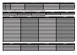
WARRANTY AND SERVICE CONTACT INFORMATION // GARANTIE UND SERVICE KONTAKTINFORMATIONEN // COORDONNÉES DE GARANTIE ET RÉPARATIONS // GARANZIA E REVISIONA INFORMAZIONI PER I CONTATTI Country of Purchase United States of America Horizon Hobby Contact Information Horizon Service Center (Repairs and Repair Requests) servicecenter.horizonhobby.com/RequestForm/ Horizon Product Support (Product Technical Assistance) www.quickbase.
AMA NATIONAL MODEL AIRCRAFT SAFETY CODE Effective January 1, 2012 A. GENERAL: A model aircraft is a non-human-carrying aircraft capable of sustained flight in the atmosphere. It may not exceed limitations of this code and is intended exclusively for sport, recreation and/or competition. All model flights must be conducted in accordance with this safety code and any additional rules specific to the flying site. 1. Model aircraft will not be flown: (a) In a careless or reckless manner.
© 2013 Horizon Hobby, Inc. E-flite, Celectra, Hangar 9, and DSMX are trademarks or registered trademarks of Horizon Hobby, Inc. The Spektrum trademark is used with permission of Bachmann Industries, Inc. The Red Bull name and likeness is used under license of Red Bull GmbH Austria. All other trademarks, service marks and logos are property of their respective owners.