® Instruction Manual Bedienungsanleitung Manuel d’utilisation Manuale di Istruzioni
EN NOTICE All instructions, warranties and other collateral documents are subject to change at the sole discretion of Horizon Hobby, LLC. For up-to-date product literature, visit www.horizonhobby.com and click on the support tab for this product.
EN Box Contents Quick Start Information Transmitter Setup Set up your transmitter using the transmitter setup table Center of Gravity (CG) 200-210mm from the nose of the airplane as shown in the Center of Gravity section (CG must be set with the motor nacelles in the multirotor flight, upright position) Flight Timer Setting 5 minutes Table of Contents Components Motors: (3) 1404-2500Kv Motors Installed Installed ESC: (3) 6 AMP Brushless ESCs Installed Installed Servo: (2) 5g Sub-Micro Analog A
EN Preflight 1. Remove and inspect contents. 9. Make sure linkages move freely. 2. Read this instruction manual thoroughly. 10. Perform the Control Direction Test with the transmitter. 3. Charge the flight battery. 11. Perform the stability system control direction test with the aircraft. 4. Setup Transmitter using transmitter setup chart. 12. Adjust flight controls and transmitter. 5. Fully assemble the airplane. 13. Perform a radio system Range Test. 6.
EN Battery Installation and ESC Arming Battery Selection We recommend the E-flite® 800mAh 11.1V 3S 30C Li-Po battery (EFLB8003S30). Refer to the Optional Parts list for other recommended batteries. If using a battery other than those listed, the battery should be within the range of capacity, dimensions and weight of the E-flite Li-Po battery packs to fit in the fuselage. 1. Lower the throttle and throttle trim to the lowest settings. Set the switches to Multirotor and Stability Mode.
EN Flight Conditions Stability and Acro Flight Modes are available in both Airplane Flight Mode and Multirotor Flight Mode. The basic function of each mode is the same regardless of what realm of flight is active. Motor Nacelle Positions Stability Mode Stability Mode limits the bank and pitch angle of the aircraft. The aircraft will self-level if you release the transmitter sticks. Acro Mode Acro Mode removes the bank angle limits and will not self-level the aircraft if you release the transmitter sticks.
EN Linkage Settings and Flight Trimming The table to the right shows the factory settings for the control horns and servo arms. Fly the aircraft at factory settings before making any changes to the elevon linkages. Control Horns Servo Arms Elevons Trim 1. With the model sitting on the ground and the motors off, verify the motor nacelles are positioned level in Airplane Flight Mode with Acro Mode.
EN Multirotor Flight Mode Aileron Aileron right Rear view Right Rear view Aileron left Rudder Left Top view Top view Yaw left Yaw right Rudder right Rudder left Airplane Flight Mode Throttle Left side view Left side view Faster Slower Throttle down Throttle up Elevator Elevator down Left side view Pitch down Aileron Aileron right Left side view Elevator up Rear view Rear view Aileron left Roll right Rudder 8 Roll left Top view Top view Yaw right Rudder right Pitch up
EN Flying Your Aircraft Consult local laws and ordinances before choosing a flying location. Range Check your Radio System Airplane Flight Before you fly, range check the radio system. Refer to your specific transmitter instruction manual for range test information. Fly the aircraft and trim it for level flight per the Trimming Your Aircraft section. The Convergence flies in a very similar manner to any other fixed-wing aircraft.
EN Post Flight 1. Disconnect the flight battery from the flight controller (Required for Safety and battery life). 5. Repair or replace all damaged parts. 2. Power OFF the transmitter. 7. Make note of the flight conditions and flight plan results, planning for future flights. 3. Remove the flight battery from the aircraft. 6. Store the flight battery apart from the aircraft and monitor the battery charge. 4. Recharge the flight battery.
EN PNP Receiver Selection and Installation The Convergence aircraft uses the Spektrum™ DSMX® serial receiver (SPM4648), included in the BNF-Basic aircraft, Installation of a DSMX serial receiver 1. Remove the bottom cover from the fuselage. 2. Mount the receiver to the fuselage as shown using double-sided servo tape or hook and loop material. 3. Attach the serial receiver lead to the receiver and to the flight control board. 4. Replace the bottom fuselage cover.
EN Troubleshooting Guide Problem Possible Cause Throttle not at idle and/or throttle trim too high Throttle servo travel is lower than 100% Throttle channel is reversed Motors disconnected from ESCs Damaged propeller or motor Extra propeller noise Propeller is out of balance or extra vibration Prop nut is too loose Flight battery charge is low Propeller installed backwards Reduced flight time or Flight battery damaged aircraft underpowered Flight conditions may be too cold Battery capacity too low for fli
EN AMA National Model Aircraft Safety Code Effective January 1, 2014 A. GENERAL A model aircraft is a non-human-carrying aircraft capable of sustained flight in the atmosphere. It may not exceed limitations of this code and is intended exclusively for sport, recreation, education and/or competition. All model flights must be conducted in accordance with this safety code and any additional rules specific to the flying site. 1. Model aircraft will not be flown: (a) In a careless or reckless manner.
EN Limited Warranty What this Warranty Covers Horizon Hobby, LLC, (Horizon) warrants to the original purchaser that the product purchased (the “Product”) will be free from defects in materials and workmanship at the date of purchase.
EN Contact Information Country of Purchase United States of America Horizon Hobby Contact Information Horizon Service Center (Repairs and Repair Requests) servicecenter.horizonhobby.com/ RequestForm/ productsupport@horizonhobby.com Horizon Product Support (Product Technical Assistance) 1608 Interstate Drive 877-504-0233 websales@horizonhobby.com 800-338-4639 Champaign, Illinois, 61822 USA Horizon Technischer Service service@horizonhobby.
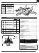
IT Exploded View / Explosionszeichnung / Vue Éclatée / Vista Esplosa 16 7 10 15 2 3 2 12 1 19 6 11 4 17 10 14 5 4 13 7 15 18 5 16 11 6 10 54 ®
Replacement Parts • Ersatzteile • Pièces de rechange • Pezzi di ricambio Part # / Nummer Numéro / Codice Description Beschreibung Description Cellule de remplacement: Mini Convergence Queue ensemble: Mini Convergence 1 EFL9301 Replacement Airframe: Mini Convergence Ersatzflugzeug: Mini Convergence 2 EFL9302 Tail set: Mini Convergence Schwanzset: Mini Convergence 3 EFL9303 Hatch Set: Mini Convergence Luken-Set: Mini-Konvergenz Hatch Set: Mini Convergence 4 EFL9304 Nacelle Set: Mini Convergence
® © 2018 Horizon Hobby, LLC. E-flite, Convergence, AS3X, DSM, DSM2, DSMX, the DSMX logo, Bind-N-Fly, BNF, the BNF logo, Plug-N-Play, ModelMatch, Dynamite, EC3, Prophet , Focal and the Horizon Hobby logo are trademarks or registered trademarks of Horizon Hobby, LLC. The Spektrum trademark is used with permission of Bachmann Industries, Inc. All other trademarks, service marks and logos are property of their respective owners. Patents pending https://www.horizonhobby.