Opterra Instruction Manual Bedienungsanleitung Manuel d’utilisation Manuale di Istruzioni SAFE® Select Technology, Optional Flight Envelope Protection 2m
EN NOTICE All instructions, warranties and other collateral documents are subject to change at the sole discretion of Horizon Hobby, LLC. For up-to-date product literature, visit www.horizonhobby.com and click on the support tab for this product.
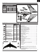
EN Box Contents Quick Start Information Transmitter Setup Elevon Throws Set up your transmitter using the transmitter setup chart elevator UP Down 15mm 16mm aileron 22mm 19mm Inline with dimples located just in front of Center of finger pockets on bottom of fuselage, slightly Gravity (CG) nose down when balanced at the dimples.
EN Preflight 1 Remove and inspect contents. 10 Perform the Control Direction Test with the transmitter. 2 Read this instruction manual thoroughly. 11 Perform the AS3X Control Direction Test with the aircraft. 3 Charge the flight battery. 12 Adjust flight controls and transmitter. 4 Setup Transmitter using transmitter setup chart. 13 Perform a radio system Range Test. 5 Fully assemble the airplane. 14 Find a safe open area to fly.
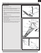
EN Model Assembly Wing Installation B 1. Slide a winglet (A) onto each wing. 2. Secure the winglet into place using the included (smaller sized) locking pin (B). Insert the pin and turn it 90 degrees to lock it into place. 3. Slide the front wing tube (short) (C) and back wing tube (D) into the fuselage. 4. Insert the vertical fin (E) into the pocket at the root of the wing (F) so the holes align and slide it onto the back wing tube (D). The vertical fins should angle outward. 5.
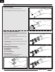
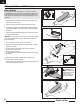
EN Optional Camera Mounts Round Nose Removal 1. Remove the 2 screws (A) from each side of the nose cone. 2. Push the tab (B) and rotate the nose down and away from the fuselage. A B Camera / FPV Camera Installation The included flat nose allows you to mount various types of cameras. The included foam inserts allow you install many types of cameras, including a GoPro or a Spektrum FPV Camera and many others. 1.
EN Optional Camera Mounts Continued FPV Transmitter Installation The FPV transmitter can be installed in the center of the fuselage as shown 1. Remove the canopy hatch from the fuselage. 2. Secure the FPV transmitter into place using hook and loop tape in the location shown. A Belly Camera Installation A GoPro camera can be mounted in the belly of the aircraft using the belly pocket. 1. Push the canopy latch button (A) to release the canopy and remove. 2.
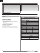
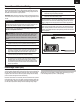
EN Control Horn and Servo Arm Settings The table to the right shows the factory settings for the control horns and servo arms. Fly the aircraft at factory settings before making changes. NOTICE: If control throws are changed from the factory settings, the AR636 gain values may need to be adjusted. Refer to the Spektrum AR636 manual for adjustment of gain values. Horns Arms Elevons After flying, you may choose to adjust the linkage positions for the desired control response. See the table to the right.
EN Transmitter and Receiver Binding Binding is the process of programming the receiver to recognize the GUID (Globally Unique Identifier) code of a single specific transmitter. You need to ‘bind’ your chosen Spektrum™ DSM2®/DSMX® technology equipped aircraft transmitter to the receiver for proper operation. IMPORTANT: Before binding a transmitter, read the Transmitter Setup section of this manual to ensure that your transmitter is properly programmed for this aircraft.
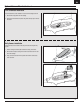
EN Battery Installation and ESC Arming Battery Selection We recommend the E-flite® 2200-3200mAh 11.1V 3S 30C Li-Po battery (EFLB32003S30). If using a battery other than those listed, the battery should be within the range of capacity, dimensions and weight of the E-flite Li-Po battery packs to fit in the fuselage. Be sure the model balances at the recommended CG. A 1. Lower the throttle and throttle trim to the lowest settings. Power on the Transmitter, then wait 5 seconds. 2.
EN Center of Gravity (CG) Establishing the correct center of gravity (CG) is very important for a successful flight experience with this aircraft. The correct CG location is identified by the molded dimples just in front of the finger pockets on the bottom of the aircraft. The aircraft will balance slightly nose down at this location. This CG location has been determined with the recommended Li-Po battery (EFLB22003S30) installed all the way forward in the battery tray.
EN In Flight Trimming During your first flight, trim the aircraft for level flight in a glide (power off). Make small trim adjustments with your transmitter’s trim switches to straighten the aircraft’s flight path. 3 Seconds After adjusting trim do not touch the control sticks for 3 seconds. This allows the receiver to learn the correct settings to optimize AS3X performance. Failure to do so could affect flight performance.
EN Post Flight 1 Disconnect the flight battery from the ESC (Required for Safety and battery life). 5 Repair or replace all damaged parts. 2 Power OFF the transmitter. 6 Store the flight battery apart from the aircraft and monitor the battery charge. 3 Remove the flight battery from the aircraft. 4 Recharge the flight battery. 7 Make note of the flight conditions and flight plan results, planning for future flights.
EN Troubleshooting Guide Problem Aircraft will not respond to throttle but responds to other controls Extra propeller noise or extra vibration Reduced flight time or aircraft underpowered Aircraft will not Bind (during binding) to transmitter Aircraft will not connect (after binding) to transmitter Control surface does not move Controls reversed Motor power pulses then motor loses power 14 Possible Cause Solution Throttle not at idle and/or throttle trim too high Reset controls with throttle st
EN AMA National Model Aircraft Safety Code Effective January 1, 2014 A. GENERAL A model aircraft is a non-human-carrying aircraft capable of sustained flight in the atmosphere. It may not exceed limitations of this code and is intended exclusively for sport, recreation, education and/or competition. All model flights must be conducted in accordance with this safety code and any additional rules specific to the flying site. 1. Model aircraft will not be flown: (a) In a careless or reckless manner.
EN Limited Warranty What this Warranty Covers Horizon Hobby, LLC, (Horizon) warrants to the original purchaser that the product purchased (the “Product”) will be free from defects in materials and workmanship at the date of purchase.
EN Contact Information Country of Purchase Horizon Hobby Horizon Service Center (Repairs and Repair Requests) United States of America Horizon Product Support (Product Technical Assistance) Sales United Kingdom Germany France Service/Parts/Sales: Horizon Hobby Limited Horizon Technischer Service Sales: Horizon Hobby GmbH Service/Parts/Sales: Horizon Hobby SAS Phone Number/Email Address servicecenter.horizonhobby.com/ RequestForm/ productsupport@horizonhobby. com. 877-504-0233 websales@horizonhobby.
Replacement Parts • Ersatzteile • Pièces de rechange • Pezzi di ricambio Part # | Nummer Numéro | Codice Description Beschreibung Description EFL11101 Foam Nose: Opterra Schaumnase: Opterra Opterra - Nez en mousse EFL11102 Camera Nose: Opterra Kameranase: Opterra Opterra - Nez pour caméra EFL11105 EFL11106 Folding Prop/Spinner: Opterra Motor Mount: Opterra Faltpropeller/Spinner: Opterra Motorhalterung: Opterra Opterra - Hélice pliable/cône Opterra - Support moteur EFL11108 Horn/Pushrod Set:
Opterra © 2016 Horizon Hobby, LLC. E-flite, Opterra, AS3X, DSM, DSM2, DSMX, the DSMX logo, Bind-N-Fly, BNF, the BNF logo, Plug-N-Play, ModelMatch, Dynamite, Prophet, EC3, SAFE, the SAFE logo, and the Horizon Hobby logo are trademarks or registered trademarks of Horizon Hobby, LLC. The Spektrum trademark is used with permission of Bachmann Industries, Inc. Futaba is a registered trademark of Futaba Denshi Kogyo Kabushiki Kaisha Corporation of Japan.