Opterra ® 1.
EN NOTICE All instructions, warranties and other collateral documents are subject to change at the sole discretion of Horizon Hobby, LLC. For up-to-date product literature, visit www.horizonhobby.com and click on the support tab for this product.
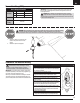
EN Box Contents with FPV EFL11460* EFL11450 EFL11475 Motor: 480 Brushless outrunner, 960Kv (EFL11407) Installed Installed Installed ESC: 18A (EFLA1030BC) Installed Installed Installed Servos: 2 Aileron Servos, (EFLR7155) Installed Installed Installed Receiver: SPM4647 Flight Controller: SPMA3235 Installed Installed Not Included GPS module: SPMA3173 Installed Not included Not Included Installed Not included Not included FPV Camera: SPMVC602 Table of Contents 21 in (525mm) SAFE®
EN SAFE® Plus Technology (BNF with FPV) There are three configurations for the Opterra 1.2m aircraft. A PNP option (EFL11475) requires pilots to install their selected control and FPV systems. A BNF Basic package (EFL11450) offers the proven SAFE® and AS3X® technologies and does not include any FPV equipment or GPS features. The BNF Basic with FPV package (EFL11460) includes SAFE Plus technology which adds GPS based features to airplanes for advanced drone-like capabilities.
EN Transmitter Setup (PNP) Basic Setup Information Dual Rates Ail Hi Rate 24mm Low Rate 16mm Ele 8mm 5mm Control Elevon mixing required Flight Timer Setting 6 minutes IMPORTANT: Elevon mixing is required for PNP versions of this aircraft. Both ailerons need to operate together as elevators and opposite as ailerons for correct flight controls. CAUTION: Do not attempt to fly the PNP version without a properly configured elevon mix.
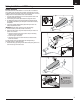
EN Model Assembly Wing Installation 1. Slide the wing tube into the fuselage. 2. Slide the wings onto the wing tube. 3. Press the wing panels together onto the fuselage until the wings click into place. 4. Insert the vertical fins into the pockets on top of the fuselage until the fins click into place. The vertical fins should angle outward. 6 Opterra ® 1.
EN Battery Installation and ESC Arming Battery Selection We recommend E-flite® 2200-3200mAh 11.1V 3S- 4S 30C Li-Po batteries. If using a battery other than those listed, the battery should be within the range of capacity, dimensions and weight of the E-flite Li-Po battery packs to fit in the fuselage. Be sure the model balances at the recommended CG. 1. Lower the throttle and leave the trim in the neutral position. Power on the transmitter, then wait 5 seconds. 2.
EN Compass Calibration Procedure (BNF with FPV) Perform the compass calibration outdoors before the first flight or to correct the heading during auto landing if it varies significantly from the heading set during takeoff. 1. Remove the propeller if it is installed or activate throttle cut. 2. With the transmitter trims centered, power on the transmitter and the aircraft while holding the transmitter sticks as shown.
EN Video System (BNF with FPV) The video transmitter installed in the BNF FPV version includes an integrated On Screen Display system (OSD). The OSD takes advantage of the GPS data available on the aircraft to deliver the pilot useful information on the video display. The OSD shows the Flight Mode, Speed and altitude, GPS status, distance to home and an arrow pointing home, time aloft, and voltage.
EN Using the Video Transmitter Specifications MODEL Transmitter Frequency (MHz) Video Format Output Impedance Output Power Input Voltage Camera Output Voltage Antenna Connector Recommended Camera SPMVT1001 SPMVT1001EU Wideband FM Modulate NTSC 50 Ohm Off, 25mW, 200mW, 600mW selectable DC 5V Wideband FM Modulate NTSC 50 Ohm DC 5V DC 5V MMCX MMCX SPMVC602 SPMVC602 3 1 2 SPMVT1000 DC 5V 1. Camera connector 2. Servo connector (Flight Controller) 3. Power LED (White) 4.
EN Install the Propeller WARNING: Do not install the propeller until the aircraft has been completely assembled, all systems have been checked thoroughly, and you are located at a suitable flying site. 1. Install the spinner backplate, propeller, prop washer and spinner adapter. 2. Tighten the spinner adapter until the propeller is securely fastened. 3. Secure the spinner with a 3 x 20mm screw. Disassemble in reverse order.
EN Flight Preparation Preflight Checklist 1. Find a safe and open flying area 2. Charge flight battery 3. Turn on transmitter 4. Install fully charged flight battery in aircraft 5. Confirm the CG is within the recommended limits 6. Ensure the linkages move freely 7. Perform control direction test 8. Perform a range check 9. Perform the compass calibration 10. Plan flight for flying field conditions 11. Verify the video display is receiving a solid signal 12. Install the propeller 13.
EN Flying Technology Flight Modes Change between SAFE Plus flight modes by changing the flight mode switch position. Safe Mode (Position 0): • Below approx. 50 feet (15m), pitch (nose up and down) and roll (wing tips up and down) angles are limited to help you keep the aircraft airborne. • Above approximately 50 feet (15m), pitch and roll control are increased slightly. • At any time release both sticks to activate panic recovery mode for self-leveling.
EN Virtual Fence Mode (BNF with FPV) CAUTION: Keep aircraft away from magnetic sources such as cameras, camera mounts, speakers ect. These may interfere with the GPS system and loss of control may result. Your aircraft uses GPS to establish a home location and a virtual fence to keep the aircraft within a given distance from the home location. While flying, the aircraft will automatically turn around and fly back towards the home location if it approaches the edge of the virtual fence.
EN Power On, GPS Initialization and Establishing Home Location (BNF with FPV) CAUTION: Keep aircraft away from magnetic sources such as cameras, camera mounts, speakers ect. These may interfere with the GPS system and loss of control may result. 1. Power on the transmitter. 2. Install a fully charged flight battery, following the instructions in the Install the Flight Battery section. The control surfaces will go move up and down, indicating the aircraft is searching for an RF link. 3.
EN Flight Patterns (BNF with FPV) Holding Pattern Mode Loiter and Holding Pattern Mode If at anytime the aircraft seems too far away, press and release the AutoLand button on the transmitter. The aircraft will maneuver to an altitude of approximately 120 feet (36m) and begin to fly a circular pattern over the home location. If Airfield Virtual Fence mode is active, the aircraft will fly to approximately 120 ft (36m) altitude and fly a circular pattern about 100 ft (30m) in front of the home location.
EN Landing When it is time to land the aircraft, either activate AutoLand mode or land the aircraft manually. Hold for 3 sec. to activate AutoLand mode AutoLand Mode (BNF with FPV) To activate AutoLand mode, press and hold the HP/AL (bind) button for 3 seconds. The aircraft will immediately turn to align itself for an upwind approach and maneuver to an altitude of approximately 65 ft (20m) and 295 ft (90m) downwind from the takeoff point.
EN Landing Landing Manually If it is necessary to land the aircraft manually: 1. Reduce the throttle to around 50% to slow the airspeed. 2. Fly the aircraft downwind past the end of the runway. 3. Turn the aircraft into the wind and line the aircraft up with the runway center line. 4. Decrease the throttle further and begin descending towards the runway, keeping the wings level during approach. Try to have the aircraft at 10ft altitude as it passes over the threshold of the runway. 5.
EN Service and Repairs WARNING: Do not perform this or any other equipment maintenance with the propeller installed on the aircraft. Serious injury or property damage could result from the motor starting inadvertently. NOTICE: Crash damage is not covered under warranty. Thanks to the EPO foam material the aircraft,is made of, repairs can be made using virtually any adhesive (hot glue, regular CA [cyanoacrylate adhesive], epoxy, etc).
EN Trouble Shooting Guide Problem Aircraft does not operate Aircraft keeps turning in one direction Aircraft does not land on heading set on initial takeoff GPS Function not operating properly Aircraft is difficult to control Possible Cause There is no link between the transmitter and receiver No GPS lock.
EN AMA National Model Aircraft Safety Code Effective January 1, 2014 A. GENERAL A model aircraft is a non-human-carrying aircraft capable of sustained flight in the atmosphere. It may not exceed limitations of this code and is intended exclusively for sport, recreation, education and/or competition. All model flights must be conducted in accordance with this safety code and any additional rules specific to the flying site. 1. Model aircraft will not be flown: b. In a careless or reckless manner. c.
EN Limited Warranty What this Warranty Covers Horizon Hobby, LLC, (Horizon) warrants to the original purchaser that the product purchased (the “Product”) will be free from defects in materials and workmanship at the date of purchase.
EN FCC Information FCC ID: BRWSPMR4648A This equipment has been tested and found to comply with the limits for Part 15 of the FCC rules. These limits are designed to provide reasonable protection against harmful interference in a residential installation. This equipment generates uses and can radiate radio frequency energy and, if not installed and used in accordance with the instructions, may cause harmful interference to radio communications.
Recommended Receivers•Empfohlene Empfänger Récepteurs Recommandés•Ricevitori Raccomandati PNP Only • Nur PNP • PNP Uniquement • Solo PNP Part # | Nummer Numéro | Codice SPMAR610 SPMAR6600T Description Beschreibung Description Descrizione AR610 6-Channel Coated Air Receiver Ummantelter AR610-6-KanalFlugzeugempfänger Récepteur aérien avec revêtement 6 canaux AR610 Ricevente aereo AR610 6 canali con rivestimento Telemetry Equipped Receivers Empfänger mit Telemetrie Récepteurs avec télémétrie Rice
Replacement Parts • Ersatzteile • Pièces de rechange • Pezzi di ricambio Part # | Nummer Numéro | Codice Description Beschreibung Bl Motor, im Uhrzeigersinn: Chroma Description Moteur Bl, sens horaire: Chroma Descrizione BLH8611 Bl Motor, Clockwise: Chroma Bl Motor, senso orario: Chroma EFL11401 Fuselage: 1.2M Opterra Rumpf: 1.2M Opterra Fuselage: 1.2M Opterra Fusoliera: 1.2M Opterra EFL11402 Wing Set: 1.2M Opterra Flügelsatz: 1.2M Opterra Jeu d'ailes: 1.2M Opterra Set ala: 1.
Optional Parts • Optionale Bauteile • Pièces optionnelles • Pezzi opzionali Part # | Nummer Numéro | Codice 88 Description Beschreibung Description Descrizione EFLA250 Park Flyer Tool Assortment, 5 pc Park Flyer Werkzeugsortiment, 5 teilig Assortiment d'outils park flyer, 5pc Park Flyer assortimento attrezzi, 5 pc EFLAEC302 EC3 Battery Connector, Female (2) EC3 Akkukabel, Buchse (2) Prise EC3 femelle (2pc) EC3 Connettore femmina x batteria (2) EFLAEC303 EC3 Device/Battery Connector, Male/Fem
© 2018 Horizon Hobby, LLC. E-flite, Opterra, DSM, DSM2, DSMX, Bind-N-Fly, BNF, the BNF logo, Plug-N-Play, AS3X, SAFE, the SAFE logo, Passport, Prophet, EC3, and the Horizon Hobby logo are trademarks or registered trademarks of Horizon Hobby, LLC. The Spektrum trademark is used with permission of Bachmann Industries, Inc. All other trademarks, service marks and logos are property of their respective owners. US 8,672,726. US 9,056,667. Other patents pending. http://www.e-fliterc.