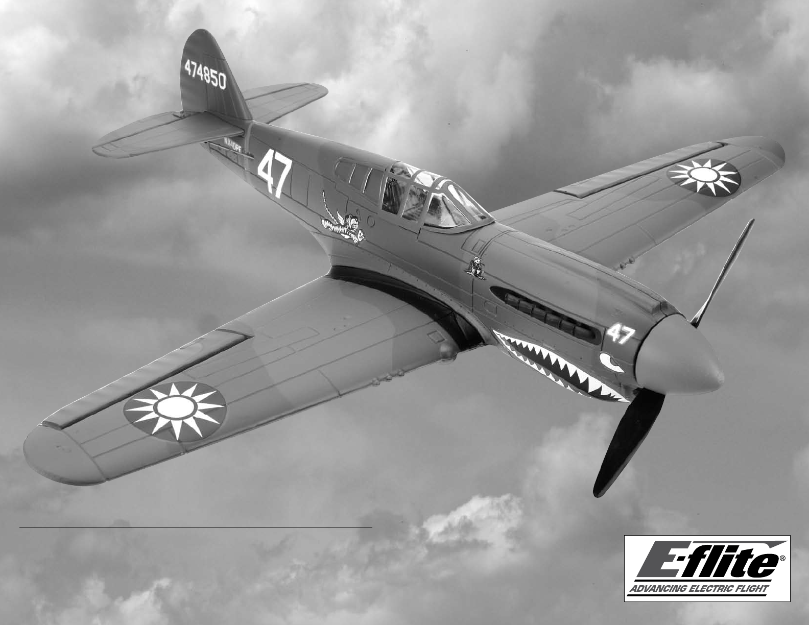
P-40 Warhawk 300 ARF Assembly Manual Specifications Wingspan: Wing Area: Length: Weight (without battery): Weight (with Li-Po Battery): 25.6 in (650mm) 108 sq in (7.02 sq dm) 21.7 in (550mm) 5.5–6.0 oz (156–170 g) 6.5–7.
Table of Contents Introduction............................................................ 2 Important Warranty Information............................... 2 Using the Manual.................................................... 2 Product Registration................................................ 2 Contents of Kit/Parts Layout..................................... 2 Recommended Radio Equipment.............................. 3 Additional Electronics..............................................
Recommended Radio Equipment You will need a minimum 4-channel transmitter, receiver, and two servos. You can also choose to purchase a complete radio system. If you are using an existing transmitter, just purchase the other required equipment separately. We recommend the crystalfree, interference-free Spektrum™ DX5e 2.4GHz DSM® 5-channel system. If you own the Spektrum DX5e radio, just add the AR6100e DSM2™ 6-channel receiver and two E-flite S60 Super Sub-Micro Servos.
4 2. Use a hobby knife with a #11 blade to cut a narrow notch at the edge of the servo pocket in the wing to allow the servo wire from the aileron servo to fit in. 3. Press the servo into the servo pocket in the wing. Make sure to guide the servo wire into the notch made in the previous step. Note that the output of the servo faces to the trailing edge (rear) of the wing. 4. Place a drop or two of foam-safe CA in the hole in the servo tab.
7. Plug the speed control and elevator servo connectors into the receiver. 8. Place a small piece of two-sided tape on the receiver. Slide the receiver into the fuselage and press it against the tape to secure it into the fuselage. Make sure to leave enough of the receiver exposed to know which port to plug the aileron servo into. 9. Connect the leads from the motor to the speed control. 11. Check the operation of your motor at this time using the radio system.
Linkage Connections 2. Use a hobby knife to enlarge the hole in a single-sided servo horn that is 9/32-inch (7mm) from the center of the servo horn. The hole needs to be big enough to insert the pushrod wire for the elevator. Use care not to make the hole too large as this will cause slop in the control system. 3. Insert the pushrod wire from the elevator into the hole enlarged in the previous step.
6. Use a hobby knife to enlarge the holes in a double-sided servo horn that is 1/2-inch (13mm) from the center of the servo horn. The hole needs to be big enough to insert the pushrod wires for the ailerons. Use care not to make the hole too large as this will cause slop in the control system. E-flite P-40 Warhawk Assembly Manual 7. Install the servo horn on the aileron linkages by inserting both linkages into the holes in the servo arm.
Wing Installation Required Parts Fuselage assembly O-ring tool 3. Position the wing on the bottom of the fuselage. The pins at the front of the wing will slide into the holes in the fuselage. 5. Use the O-ring tool to pull the O-ring upward so it can be hooked onto the tab at the rear of the cockpit as shown. Wing assembly Before installing the wing stretch the O-ring slightly by holding the base of the mount in the wing and pulling tension on the O-ring.
Battery Installation Required Parts Assembled airframe Spinner Installation 3. Place the canopy back on the fuselage. Motor battery 1. Slide the motor battery into the fuselage. It should slide in easily with little force. Required Parts Fuselage assembly Spinner Required Tools Nut driver: 5mm Canopy glue Please note that your spinner is not glued on from the factory. It is just slid on to the prop and needs to be removed and glued on for saftey. 1.
Propeller and Spinner Removal and Replacement Required Parts Fuselage assembly Spinner Required Tools Nut driver: 5mm 2. Use a 5mm nut driver to remove the nut holding the propeller on the motor. 3. Remove the washer and propeller from the motor. 4. Before installing a new propeller, make sure it is installed in the correct direction. One side will have a hex that keys to the motor. Make sure it installed with this hex toward the motor. 5. Slide the propeller on the motor shaft.
6. Next, slide the washer back on the motor shaft. Thread the 5mm locknut back on the shaft. 8. Apply a small amount of canopy glue to the nut. Use a small amount so the spinner can be easily removed if the propeller requires replacement. Display Stand Assembly Required Parts Assembled airframe Display stand strut 7. Use a 5mm nut driver to tighten the nut holding the propeller on the motor. E-flite P-40 Warhawk Assembly Manual Display stand base 1.
2. The mount for the plane can swivel on the display stand strut. This allows you to position your model for the best dramatic effect while on display. 12 Control Throws 3. The plane will rest on the mount. The straight pin on the mount is inserted into the hole in the area of the finger grips as shown. 4. With the stand and plane upright, you are now able to display your model when you are not out flying sorties. 1. Turn on the transmitter and receiver of your model. 2.
Range Test Your Radio 1. Before each flying session, be sure to range check your radio. See your radio manual for the recommended range and instructions for your radio system. Each radio manufacturer specifies different procedures for their radio systems. Next, start the motor. With the model securely anchored, check the range again. The range test should not be significantly affected. If it is, don’t attempt to fly! Have your radio equipment checked out by the manufacturer. 2.
Safety, Precautions and Warnings As the user of this product, you are solely responsible for operating it in a manner that does not endanger yourself and others or result in damage to the product or the property of others. Carefully follow the directions and warnings for this and any optional support equipment (chargers, rechargeable battery packs, etc.) that you use. This model is controlled by a radio signal that is subject to interference from many sources outside your control.
Questions, Assistance, and Repairs Your local hobby store and/or place of purchase cannot provide warranty support or repair. Once assembly, setup or use of the Product has been started, you must contact Horizon directly. This will enable Horizon to better answer your questions and service you in the event that you may need any assistance. For questions or assistance, please direct your email to productsupport@horizonhobby.com, or call 877.504.0233 toll free to speak to a service technician.
CE Compliance Information for the European Union Instructions for Disposal of WEEE by Users in the European Union This product must not be disposed of with other waste. Instead, it is the user’s responsibility to dispose of their waste equipment by handing it over to a designated collection point for the recycling of waste electrical and electronic equipment.
4. At all flying sites a line must be established, in front of which all flying takes place. Only personnel associated with flying the model aircraft are allowed at or in front of the line. In the case of airshows demonstrations straight line must be established. An area away from the line must be maintained for spectators. Intentional flying behind the line is prohibited. 10.
E-flite P-40 Warhawk Assembly Manual 19
© 2009 Horizon Hobby, Inc. 4105 Fieldstone Road Champaign, Illinois 61822 U.S.A. (877) 504-0233 horizonhobby.com E-fliteRC.