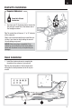
™ UMX F-16 Instruction Manual Bedienungsanleitung Manuel d’utilisation Manuale di Istruzioni
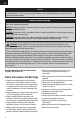
EN NOTICE All instructions, warranties and other collateral documents are subject to change at the sole discretion of Horizon Hobby, LLC. For up-to-date product literature, visit www.horizonhobby.com and click on the support tab for this product.
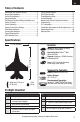
EN Table of Contents Transmitter and Receiver Binding..........................4 Missile Rail Installation .........................................4 Ventral Fin Installation...........................................5 Decal Installation ..................................................5 ESC/Receiver Arming, Battery Installation and Center of Gravity ...................................................6 Control Centering .................................................7 Factory Control Horn Settings......
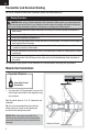
EN Transmitter and Receiver Binding For a list of compatible DSM2/DSMX transmitters, please visit www.bindnfly.com Binding Procedure CAUTION: When using a Futaba transmitter with a Spektrum DSM® module, you must reverse the throttle channel and rebind. Refer to your Spektrum module manual for binding and failsafe instructions. Refer to your Futaba transmitter manual for instructions on reversing the throttle channel. 1.
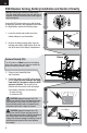
EN Ventral Fin Installation Required Adhesives: Foam Safe CA and Accelerator. 1. Use foam safe CA (Cyanoacrylate) to secure the left and right ventral fins to the bottom side of the fuselage as shown. Tip: The ventral fins will have an “L” or “R” indicator on the underside. Tip: It is not recommended that you install the ventral fins if you intend on belly landing the aircraft. Aircraft damage may result.
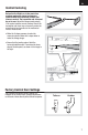
EN ESC/Receiver Arming, Battery Installation and Center of Gravity NOTICE: Always keep material or debris away from the intake. When armed, the rotor will turn in response to throttle movement and could ingest in any loose objects. 1 Arming the ESC/receiver also occurs after binding as previously described, but subsequent connection of a flight battery requires the following steps. 1. Lower the throttle and throttle trim to the lowest settings on your transmitter. 2 A 2.
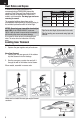
EN Control Centering Before the first flights, or in the event of an accident, make sure control surfaces are centered when the transmitter controls and trims are neutral. The transmitter sub-trim must be set to zero. Adjust the linkages mechanically if the control surfaces are not centered. Use of the transmitter sub-trims may not correctly center the aircraft control surfaces due to the mechanical limits of linear servos. • Make the U-shape narrower to make the connector shorter.
EN Dual Rates and Expos To obtain the best flight performance, we recommend using a DSM2/DSMX transmitter capable of Dual Rates and Expo. Before binding, ensure that you are starting with a blank acro model in your transmitter. Set wing type and servo reversing to normal. The suggested settings shown here are the recommended starting settings. Adjust according to the individual preferences after the initial flight. NOTICE: Do not set your transmitter travel adjust over 100%.
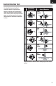
EN Control Direction Test Transmitter Command Aircraft Reaction Elevator Down Elevator Up Elevator Aileron Right Roll Left Roll Right Rudder Rudder You should bind your aircraft and transmitter before doing these tests. Move the controls on the transmitter to make sure the aircraft control surfaces move correctly and in the proper direction. Make sure the tail linkages move freely and that paint or decals are not adhered to them.
EN AS3X Direction Test You should bind your aircraft and transmitter before doing these tests. Move the controls on the transmitter to make sure the aircraft control surfaces move correctly and in the proper direction. Make sure the tail linkages move freely and that paint or decals are not adhered to them. Aircraft movement AS3X Reaction Arrows indicate the direction of the trailing edge of the control surface.
EN Flying Tips and Repairs Range Check your Radio System After final assembly, range check the radio system with the aircraft. Refer to your specific transmitter instruction manual for range test information. Flying We recommend flying your aircraft outside in no greater than moderate winds or inside in a very large indoor facility. Always avoid flying near houses, trees, wires and buildings. Be careful to avoid flying in areas where there are many people, such as busy parks, schoolyards or soccer fields.
EN Post Flight Checklist 1. Disconnect the flight battery from the ESC (Required for safety and battery life). 5. Store the flight battery apart from the aircraft and monitor the battery charge. 2. Power OFF the transmitter. 6. 3. Remove the flight battery from the aircraft. Make note of the flight conditions and flight plan results, planning for future flights. 4. Recharge the flight battery.
EN Troubleshooting Guide (Continued) Problem Possible Cause Solution LED on receiver flashes Less than a 5-second wait between first rapidly and aircraft will powering on transmitter and connecting not respond to transmit- flight battery to aircraft ter (after binding) Aircraft bound to different model memory (ModelMatch™ radios only) Control surface does not move Leaving transmitter on, disconnect and reconnect flight battery to aircraft Select correct model memory on transmitter and disconnect and recon
EN Horizon reserves the right to inspect any and all Product(s) involved in a warranty claim. Service or replacement decisions are at the sole discretion of Horizon. Proof of purchase is required for all warranty claims. SERVICE OR REPLACEMENT AS PROVIDED UNDER THIS WARRANTY IS THE PURCHASER’S SOLE AND EXCLUSIVE REMEDY.
EN will not be serviced. Further, the sender will be responsible for arranging return shipment of the un-serviced Product, through a carrier of the sender’s choice and at the sender’s expense. Horizon will hold non-compliant Product for a period of 60 days from notification, after which it will be discarded.
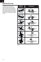
Replacement Parts – Ersatzteile – – Pièces de rechange – Recapiti per i ricambi – Part # • Nummer Numéro • Codice Description Beschreibung Description Descrizione EFLU2846 Pushrod Linkage Set: UMX F-16 E-Flite UMX F-16: Gestängeset UMX F-16 - Tringleries Set aste comandi: UMX F-16 EFLU2855 Landing Gear Set: UMX F-16 E-Flite UMX F-16: Fahrwerkset UMX F-16 - Train d’atterrissage Set carrello: UMX F-16 Fuselage with Accessories: UMX F-16 E-Flite UMX F-16: Rumpf mit Zubehör UMX F-16 - Fuselage
– Optional Parts and Accessories – – Optionale Bauteile und Zubehörteile – – Pièces optionnelles et accessoires – – Parti opzionali e accessori – Part # • Nummer Description Numéro • Codice Beschreibung Description Descrizione PKZ1039 Hook and Loop Set (5): Ultra Micros Klettband (5): Ultra Micros Bande autoagrippante (5) Set fascette fissaggio (5): Ultra Micros EFLUC1007 Celectra 2S 7.4V DC Li-Po Charger Celectra 2S 7.4V DC Li-Po Ladegerät Celectra Chargeur Li-Po 7.4V 2S Celectra 2S 7.
™ UMX F-16 © 2015 Horizon Hobby, LLC. E-flite, AS3X, UMX, Delta-V, DSM, DSM2, DSMX, ModelMatch, Bind-N-Fly, Celectra and the Horizon Hobby logo are trademarks or registered trademarks of Horizon Hobby, LLC. The Spektrum trademark is used with permission of Bachmann Industries, Inc.