Viking Model 12 Instruction Manual Bedienungsanleitung Manuel d’utilisation Manuale di Istruzioni ® 280
EN NOTICE All instructions, warranties and other collateral documents are subject to change at the sole discretion of Horizon Hobby, LLC. For up-to-date product literature, visit www.horizonhobby.com and click on the support tab for this product.
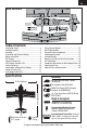
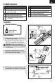
EN Box Contents Table of Contents Transmitter Setup .................................................4 Preflight Checklist .................................................5 Assembly ..............................................................5 Transmitter and Receiver Binding .........................7 Battery Installation ................................................8 ESC Arming ..........................................................8 Control Direction Test .......................................
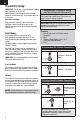
EN Transmitter Setup IMPORTANT: Set up your transmitter before binding your transmitter to the aircraft. Before binding a non-computerized transmitter, ensure all servo reversing is set to normal and trim is at center. Dual Rates and Expo After first flights, you may adjust Dual Rates and Expo in your transmitter or refer to the AR6335 receiver manual for Dual Rates and Expo adjustment.
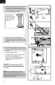
EN Preflight Checklist 1. Charge flight battery. 6. Adjust center of gravity. 2. Install flight battery in aircraft (once it has been fully charged). 7. Perform a radio system Range Check. 3. Bind aircraft to transmitter. 8. Find a safe and open area. 4. Make sure linkages move freely. 9. Plan flight for flying field conditions. 5. Perform Control Direction Test with transmitter. Assembly Required Adhesives: foam-compatible Medium CA Wing Installation 1.
EN 4. Apply foam-compatible medium CA to the strut mounting slots on both wings. Slide the left and right struts in the slots between the wings as shown. Make sure the wings are straight, level and parallel with each other. The blue graphic should be at the top of the strut with the decal at the bottom facing out. 5. Secure the top wing to the fuselage by applying foam-compatible medium CA where the upper wing cabane rods meet the fuselage mounts. 6.
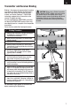
EN Transmitter and Receiver Binding Binding is the process of programming the receiver to recognize the GUID (Globally Unique Identifier) code of a single specific transmitter. You need to ‘bind’ your chosen Spektrum™ DSM2/DSMX technology equipped aircraft transmitter to the receiver for proper operation. Any full range Spektrum DSM2/DSMX transmitter can bind to the DSM2/DSMX receiver. Please visit www.bindnfly.com for a complete list of compatible transmitters.
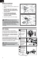
EN Battery Installation 1. Remove the battery hatch. 2. Apply hook and loop tape to the bottom of the battery. 3. Install the battery (A) in the battery cavity towards the front of the fuselage. Refer to the Center of Gravity instructions for the battery’s position. 4. Connect the fully charged flight battery to the ESC. Refer to the ESC Arming instructions for correct connection of the battery to the ESC. 5. Replace the battery hatch on the fuselage.
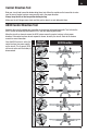
EN Control Direction Test Bind your aircraft and transmitter before doing these tests. Move the controls on the transmitter to make sure the aircraft control surfaces move correctly and in the proper direction. Always keep throttle at the low position during testing. Make sure the tail linkages move freely and that paint or decals are not adhered to them. AS3X Control Direction Test Assemble the aircraft and bind your transmitter to the receiver before performing this Test.
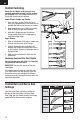
EN Control Centering Before the first flights, or in the event of an accident, make sure the flight control surfaces are centered. Adjust the linkages mechanically if the control surfaces are not centered. Lower Ailerons, Rudder and Elevator 1. Reset sub-trims to zero. Ensure the servo arms are as perpendicular to the servo case as possible. Use sub-trim to fine-tune as needed. 2 When needed, use a pair of pliers to carefully bend the metal linkage (see illustration). 3.
EN Center of Gravity (CG) The CG location is 45mm back from the leading edge of the wing at the wing root. The battery compartment is oversized to allow for Center of Gravity adjustment. Start by installing the battery fully forward with the connectors facing the front of the aircraft. Adjust as needed by sliding the battery back. 45mm Low Voltage Cutoff (LVC) When a Li-Po battery is discharged below 3V per cell, it will not hold a charge.
EN Flying Tips and Repairs Consult local laws and ordinances before choosing a location to fly your aircraft. We recommend flying your aircraft outside in no greater than moderate winds. Always avoid flying near houses, trees, wires and buildings. You should also be careful to avoid flying in areas where there are many people, such as busy parks, schoolyards or soccer fields. Range Check Your Radio System After final assembly, range check the radio system with the aircraft.
EN Service of Power Components Disassembly CAUTION: Always disconnect the battery before handling or adjusting the propeller or motor. Failure to do so could result in personal injury. A B C F Propeller 1. Remove the 2 screws (A) from the spinner (B). Carefully separate the spinner from the back plate (C). E 2. Remove the lock nut (D) from the propeller shaft (E), then remove the propeller (F) and back plate. D 3.
EN Troubleshooting Guide Problem Aircraft will not respond to throttle but responds to other controls Extra propeller noise or extra vibration Possible Cause ESC did not arm because throttle stick and/or throttle trim too high Throttle channel is reversed Motor disconnected from ESC Servo travel setup is less than 100% Damaged propeller, spinner or motor Prop nut is too loose Prop is out of balance Spinner is not tight or fully seated in place Reduced flight time or aircraft underpowered Aircraft will no
EN Limited Warranty What this Warranty Covers Horizon Hobby, LLC (“Horizon”) warrants to the original purchaser that the product purchased (the “Product”) will be free from defects in materials and workmanship at the date of purchase.
EN If received, a non-compliant Product will not be serviced. Further, the sender will be responsible for arranging return shipment of the un-serviced Product, through a carrier of the sender’s choice and at the sender’s expense. Horizon will hold non-compliant Product for a period of 60 days from notification, after which it will be discarded.
Replacement Parts – Ersatzteile – – Pièces de rechange – Pezzi di ricambio – Part # • Nummer Numéro • Codice Description Beschreibung Description EFL6651 Fuselage w/ Rudd/Tailwheel/ Hatch: Viking Model 12 E-flite Viking Model 12: Rumpf m. SR. Spornr.
– Optional Parts and Accessories – – Optionale Bauteile und Zubehörteile – – Pièces optionnelles et accessoires – – Parti opzionali e accessori – Part # • Nummer Description Numéro • Codice Beschreibung Description Descrizione EFLA230 Charger Lead with JST Female E-flite Ladekabel m/ JST Buchse Câble de charge avec prise JST femelle Cavo di carica con femmina JST EFLA250 Park Flyer Tool Assortment, 5 pc Park Flyer Werkzeugsortiment, 5 teilig Assortiment d’outils park flyer, 5pc Park Flyer assorti
© 2014 Horizon Hobby, LLC. E-flite, Prophet, DSM, DSM2, DSMX, AS3X, ModelMatch, and the BNF logo are trademarks or registered trademarks of Horizon Hobby, LLC. The Spektrum trademark is used with permission of Bachmann Industries, Inc. MODEL 12® is a registered trademark used by permission of Jim Kimball Enterprises, Inc. Futaba is a registered trademark of Futaba Denshi Kogyo Kabushiki Kaisha Corporation of Japan. Patents pending. www.e-fliterc.