Q U I C K S T A R T IM-E/IM-V Series Network Dome Camera Sarix™ Technology C2983M-A (12/10)
Contents Product Overview . . . . . . . . . . . . . . . . . . . . . . . . . . . . . . . . . . . . . . . . . . . . . . . . . . . . . . . . . . . . . . . . . . . . . . 3 Installation . . . . . . . . . . . . . . . . . . . . . . . . . . . . . . . . . . . . . . . . . . . . . . . . . . . . . . . . . . . . . . . . . . . . . . . . . . . 5 Operation . . . . . . . . . . . . . . . . . . . . . . . . . . . . . . . . . . . . . . . . . . . . . . . . . . . . . . . . . . . . . . . . . . . . . . . . . . .
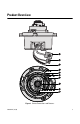
Product Overview Figure 1.
ì RJ-45 Network Port: Connects the camera to the IP network. Also supplies power to the camera through the network using PoE. î Accessory Port: For use with compatible Pelco accessories. ï Audio Line-In and Line-Out: Supplies line-in and line-out audio connections from a user-supplied device. Audio functionality is only available for IM10-E and IM10-V Series models, and it can be enabled or disabled using the Web browser. ñ Microphone: Supplies built-in, line-in audio to a PC.
Installation 1. Prepare the mounting surface: a. Cut a 4-inch (10.16 cm) diameter hole in the ceiling/wall. b. Pull all wiring through the hole and terminate all wires (if not already terminated). 2. Connect the network cable to the RJ-45 network port on the side of the camera. Pin 1 1 8 8 2 3 4 5 6 7 1 8 8 7 6 Function 1 TX+ 2 TX– 3 RX+ 4 PoE 1-2 5 PoE 1-2 6 RX– 7 PoE 3-4 8 PoE 3-4 5 4 3 2 1 Figure 2. Cat5 Cable Pin Descriptions 3.
+ – Figure 4. Line-Out Audio Wiring ì Speaker î Amplifier ï 600-Ohm Impedance Matching Transformer ñ Line Out – (Red) ó Line Out + (Orange) 4. Install the back box: a. Insert the back box into the hole in the ceiling/wall. Be sure to angle the back box during this step to ensure that the wiring is inserted into the hole first and is not bent or damaged. b. Use two 3/16-inch toggle bolts (not supplied) to attach the back box to the mounting surface (refer to Figure 5). Figure 5.
6. Position the camera as needed: a. View the camera image using the service port. b. Manually rotate and tilt the camera module to position the camera. Do not over-rotate the module. WARNING: Excessively turning the module in one direction could result in damage to the wiring. Figure 6. Adjusting the Pan and Tilt ì Pan 355° î Rotate 120° ï Tilt 164° 7. Adjust the field of view: a. Loosen the zoom locking screw. b. Turn the zoom adjustment ring clockwise or counterclockwise to adjust the field of view.
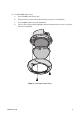
9. Align the dome liner with the camera, and then snap it into place. Figure 7.
10. Install the bubble and trim ring: a. Place the bubble inside the trim ring. b. Align the trim ring screws with the three mounting screw holes on the back box. c. Push the bubble and trim ring onto the back box. d. Use the 1/8-inch hollow hex bit (supplied) to tighten the tamper-resistant screws to secure the trim ring to the back box. Figure 8.
Operation IP ADDRESS SETTINGS If the camera is connected to a Dynamic Host Configuration Protocol (DHCP) network and DHCP is set to the On position, the server will automatically assign an IP address to the device; DHCP On is the default setting for the camera. Set DHCP to the Off position to manually set the camera’s IP address. NOTES: • If the camera is not connected to a DHCP server but DHCP is set to On, the default IP address 192.168.0.20 on subnet mask 255.255.255.
LIVE PAGE ICONS Viewable icons are based on group permissions. Show Device List: Displays a list of viewable cameras connected to the same VLAN as the camera to which you are logged on. Disable Viewer: Closes the live view window. 1 x 1 Mode: Displays a single video pane. 2 x 2 Mode: Displays 4 video panes in rows of two. 3 x 3 Mode: Displays 9 video panes in rows of three. 4 x 4 Mode: Displays 16 video panes in rows of four.
SETTINGS PAGE Depending on user permissions, the Settings page allows you to manage camera system settings, set up users and groups, and control the camera. To access the camera settings: 1. Log on to the camera. 2. Click the Settings link in the navigation bar located in the upper-right corner of the page; a list of menu tabs appear. 3. Place the mouse pointer over a tab to display a list of submenus.
IMAGING TAB General: Includes camera orientation and digital processing settings. The orientation settings allow for standard or inverted installation of the camera. The digital processing settings adjust the sharpness, saturation, and contrast of the scene. Exposure: Adjusts scene detail and contrast. A scene with correct exposure settings has adequate detail and contrast between white and dark values. An image with too little or too much exposure eliminates detail in the scene.
A/V STREAMS TAB Use the A/V Streams tab to configure the video and audio streams for the camera. The A/V Streams tab includes a Video Presets page, a Video Configuration page, and an Audio Configuration page. Video Presets: The Video Preset page includes three fully-configured video presets, which include primary and secondary video stream settings for easy setup. These presets may also be used as a starting point for a custom video configuration. These preset configurations vary depending on camera model.
EVENTS TAB Sources: Defines the camera functions that are automatically triggered by an event source. The camera supports Alarm, Analytics, System, and Timer event sources. Handlers: Defines the actions that a camera takes when an event occurs. The camera supports four event handlers: Send Email, Upload JPEG to FTP Server, and Open/Close Relay. Analytic Configuration: Allows you to create custom profiles that contain different camera settings.
www.pelco.