
Specifications


C2983M-A (12/10) 5
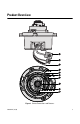
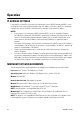
Installation
1. Prepare the mounting surface:
a. Cut a 4-inch (10.16 cm) diameter hole in the ceiling/wall.
b. Pull all wiring through the hole and terminate all wires (if not already terminated).
2. Connect the network cable to the RJ-45 network port on the side of the camera.
Figure 2. Cat5 Cable Pin Descriptions
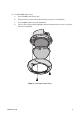
3. If you are installing an IM10-V or IM10-E Series model, connect the necessary wiring for audio.
Figure 3. Line-In Audio Wiring
Pin Function
1TX+
2TX–
3RX+
4 PoE 1-2
5 PoE 1-2
6RX–
7 PoE 3-4
8 PoE 3-4
ì
Microphone
î
Amplifier
ï
600-Ohm Impedance Matching Transformer
ñ
Line In – (White)
ó
Line In + (Brown)
1
2
3
4
5
6
7
8
1
2
3
4
5
6
7
8
8
8
1
1
+
–