
Specifications
PROPRIETARY DATA: This document contains proprietary data of ABB Inc. No disclosure, distribution (electronic or otherwise),
or other means of dissemination may be made without written permission.
3BUS 208 000 R1301 95Platform Tuning
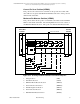
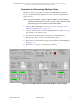
Determining and Entering the Head Dimensions
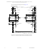
Refer to Table 5-4 on page 96 and Figure 5-14 on page 91.
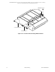
1. Split the sensor heads, using one of the head split switches. Head split switches
are located in the drive end and idler end columns.
2. Measure and record the homeHeadClearance and the farHeadClearance (in
customer units) from the Scanning Platform head package.
3. Enter the values for homeHeadClearance and farHeadClearance into the
Frame Health Report. Refer to Figure 5-14.
homeHeadClearance and farHeadClearance assist the servo in making sure
the head is sufficiently inside the sheet before measuring. These dimensions
can be adjusted instead of curlDist to suit a desired head position during Prepare
to Measure operations.
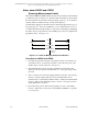
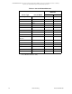
4. Determine the values for farWindowClearance and homeWindowClearance
from Figure 5-15 on page 94. Table 5-4 on page 96 gives typical measurement
area diameters for each sensor.
5. Divide the value for the largest sensor beam diameter by 2 to get the
farWindowClearance and homeWindowClearance.
6. Enter the resultant number into the HEAD SETUP section of the Frame Health
Report. Refer to Figure 5-14.
7. Exit the Health Report program.
8. Use the gstore procedure to save the changes made on the Frame Health Report.
Note: The diameters given in Table 5-4, define the nominal dimensions of
the various sensor measurement beams. Each sensor has its own
unique tolerance characteristics as the beam encroaches over a
sheet edge. These characteristics will govern, in part, how close the
measurement centerline may be brought to the sheet edge. For
example, a GT Caliper probe may not go beyond the edge. On the
other hand, a HemiPlus IR beam can be as much as halfway over
the edge. Check each sensor’s technical manual for that sensor’s
tolerance.