
Specifications
PROPRIETARY DATA: This document contains proprietary data of ABB Inc. No disclosure, distribution (electronic or otherwise),
or other means of dissemination may be made without written permission.
3BUS 208 000 R1301182 Maintenance Procedures
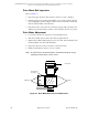
1. Inspect the seal belts for evidence of wear or cracks. Replace belts that have
evidence of wear or cracks.
2. Inspect the seal belt rollers for evidence of cracks or wear.
3. Inspect the spring tension on the seal belt rollers. The roller assembly should
exert some downward force when manually lifted. If this does not happen, the
roller assembly should be replaced.
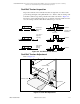
If the seal belt tension is uneven, adjust the tension of the seal belt as follows:
1. Loosen the seal belt clamp adjustment corresponding to the side that is elevated
by a slight amount.
2. Tighten the clamp when finished.
If the belt tension is too tight at both sides:
1. Loosen the seal belt clamp adjustments and pull the seal belt evenly in the cross–
machine direction to result in a uniform decrease in tension.
2. Tighten the clamps when finished.
If the belt tension is too loose:
1. Loosen the seal belt clamp and pull the seal belt through the clamp in the cross–
machine direction evenly to result in a uniform increase in tension.
2. Tighten the clamp when finished.
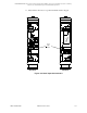
Head Separation and Limit Switch Inspection
Refer to Figure 9-6 on page 183. Verify the operation of the head separation clutch
by completing the following:
1. Move the sensor head package to the off-sheet position.
2. Place the platform in Local by pressing the LOCAL push button on the control
panel.
3. Verify that the shutter closes on the Basis Weight and Ash sensors.
4. Activate the head separation switch located at either end of the Scanning
Platform in the service outlet box.
5. Make sure the sensor heads can be separated by manually moving the bottom
head.
6. Move the sensor heads back as close as possible to their original position.
7. Return the air clutch swith to its original position.
8. Manually position the sensor heads to make sure the air clutch has been properly
seated and locks when the proper position is reached.
9. Return to the normal system operation.
10. Manually jog the sensor package to the drive and idler ends slowing the rate of
travel as they reach the end of the platform.