
Specifications


PROPRIETARY DATA: This document contains proprietary data of ABB Inc. No disclosure, distribution (electronic or otherwise),
or other means of dissemination may be made without written permission.
3BUS 208 000 R1301 205Replacement Procedures
Electric Chassis
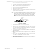
There have been several reported occurrences of the MP
power flex cable being plugged in wrong. A typical error
puts 120 VAC where the ± 15 VDC is supposed to be. If
the system is powered up with the power cable plugged
in wrong, catastrophic failure of sensors is likely.
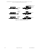
Electric Chassis Replacement Procedure
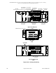
Complete the following procedure to replace the electric chassis in the upper or
lower carriage. Refer to Figure 10-12.
1. Jog sensor heads to the Scanning Platform idler end.
2. Turn Off power to the Scanning Platform.
3. Remove the carriage end cover, then pull out the electric chassis.
4. Remove the cable connectors for the sensor interconnection.
5. Remove the ribbon cable connectors for the cable suspension from the carriage
electric chassis.
6. Replace ribbon cable connectors for the cable suspension.
7. Replace the cable connectors for the sensor interconnection.
8. Slide the replacement electric chassis in place.
9. Replace the carriage end cover.
10. Turn On power to the Scanning Platform.