
Specifications


PROPRIETARY DATA: This document contains proprietary data of ABB Inc. No disclosure, distribution (electronic or otherwise),
or other means of dissemination may be made without written permission.
3BUS 208 000 R1301 43Hardware Installation
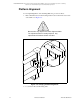
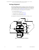
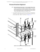
3. Adjust the inner jackscrews on the end column to zero the level at one column,
and repeat for the column at the other end of the platform.
Maintain the same orientation of the machinist’s level at both ends of the
platform.
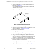
4. Check the position of the wire in the air gap to assure that the pass line angle
is unchanged. Should the angle appear to have changed, repeat Step 3.
5. Adjust the outside jackscrews down against the mounting support.
The adjusted jackscrews should be snug, but they should not lift the platform
off the front (inner most) jackscrews which are already precisely set.
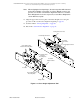
6. Place the machinist level on the leveling blocks to monitor the final settings
and to make certain no changes in leveling occur.
7. When all four jackscrews at one of the columns are adjusted satisfactorily,
tighten the hold-down mounting bolts to secure the Scanning Platform to the
support structure.
Do not over stress the mounting bolts.
8. Repeat Steps 1. through 7. for the other column.
9. Remove the wires.
This completes the Scanning Platform alignment.