
Specifications


PROPRIETARY DATA: This document contains proprietary data of ABB Inc. No disclosure, distribution (electronic or otherwise),
or other means of dissemination may be made without written permission.
3BUS 208 000 R130150 Hardware Installation
Air Gap Alignment
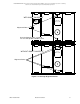
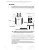
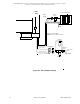
Refer to Figure 3-13 on page 47 and Figure 3-15 while performing the air gap
alignment procedure.
1. Use the vertical adjustment bolt to achieve a 7.5 ± 0.5 mm (0.295 ± 0.020 in.)
cold air gap between the base plates along the on-sheet end of the sensors and
at the points designated in Figure 3-15. For every half turn of a vertical
adjustment bolt, do a half turn to its opposite adjustment bolt. Across the sensor
window, check the distance using the air gap tool provided with the platform.
If bolts seem to bind at any time, adjust the opposite side air gap before
proceeding.
Note: You need to protect the carriage assembly from damage from
mechanical forces by not positioning the vertical adjustment bolts
such that the weight of the carriage is supported on three bolts
instead of four as this may twist the carriage. Also, never rest the
upper head package weight on the lower head package by leaving
the air gap tool between the sensors.
2. Adjust the off–sheet side air gap to 7.5 ± 0.5 mm (0.295 ± 0.020 in.) cold.
3. Continue to adjust the vertical adjustment bolts until the specified air gap is
achieved.
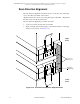
4. After acceptable air gap is set, make certain the sensor is still aligned in the
process direction. See the “Process Direction Alignment” on page 48.
5. Tighten the bolts which have large parallel face washers onto the upper adapter
plate.
6. Replace bolts with eccentrics.
7. Rotate the eccentrics on the adapter plate extension so that they bear the weight
of the upper head assembly.
8. Tighten the bolts that hold the eccentrics in place.
9. To insure that the top electrical covers will fit, the alignment mechanism should
be centered over the adapter plates.
a. Loosen adapter plate extension mounting bolts.
b. Use the horizontal alignment bolt to center the alignment mechanism over
the adapter plates.
c. Center the horizontal alignment rod in its slot.
d. Tighten the extension mounting bolts.
10. Tighten the bolts on the adapter plate, both sides.
11. Replace the electrical covers.
This completes the Air Gap Alignment Procedure.