
Specifications


PROPRIETARY DATA: This document contains proprietary data of ABB Inc. No disclosure, distribution (electronic or otherwise),
or other means of dissemination may be made without written permission.
3BUS 208 000 R1301 53Hardware Installation
The machined ears should be flush within ± 0.005 in.. If they are not:
a. Loosen the upper drive belt pulley locking screws.
b. Adjust set screws for phasing of the pulley until the heads are parallel.
c. Tighten the screws when finished.
3. Jog the heads near the idler end column.
4. Apply a straight edge and feeler gauge to the machined surface on the upper
and lower heads.
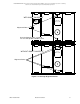
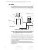
5. If they are not aligned in the scan direction within ± 0.010 in., adjust the belt
tension in the upper or lower belts by means of the idler bracket adjustment
screws. See Figure 3-17.
Figure 3-17 Scan Direction Adjustment
6. Use belt tensiometer (Part Number 122146-004) to check the belt tension. The
range is specified on the tensiometer.
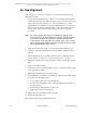
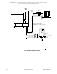
Note: The belt may be installed in such a way that the upper and lower
heads are off by more than one tooth on the belts. This can be
corrected by inserting a short strip of thin sheet metal or hard plastic
between the belt and drive pulley and allows for manual alignment
to the next tooth. See Figure 3-18.
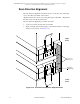
Drive
End
Idler
End
Idler End Belt
Tension Adjustments
Adjust belt tension
of idler pulley
to make heads
parallel here
Drive Pulley Lock –
Loosen to rotate pulley
for Phase Adjustment.
Adjust phase
of drive pulley
to make heads
parallel here