
Specifications


PROPRIETARY DATA: This document contains proprietary data of ABB Inc. No disclosure, distribution (electronic or otherwise),
or other means of dissemination may be made without written permission.
3BUS 208 000 R130162 Utility Service Installation
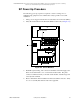
The neutral to ground bond is extremely important. If it
is not correct, the electronic filter in the ASPC may be
destroyed when power is applied.
5. Verify there is a neutral to ground bond at the SPDC, and ONLY at the SPDC.
Ensure that the primary and secondary are correctly terminated.
6. Remove the lock-out on the MCC and turn on the power to the SPDC. Measure
the primary voltages (phase to phase, phases to neutral, and phases to ground)
to verify proper power, grounding, and tap selection.
7. Turn on the SPDC main circuit breaker and measure the secondary voltages
(phase to phase, phases to neutral, and phases to ground). The output must be
240 VAC ± 10% phase to phase; and 120 VAC ± 10% each phase to neutral and
each phase to ground.
8. Turn on the SPDC circuit breaker for the purge blower. Verify that the blower
starts. Check that the voltage at the blower is 240 VAC +10%, -14%. Verify
there is air flow inside the idler end column of the SP.
9. Turn on the SPDC circuit breaker for the Liquid Cooling Unit (LCU). Verify
that the coolant starts circulating. Check that the voltage at the LCU is 240
VAC +10%, -14%. Check for leaks.
10. Measure the input voltages on the line side of the Scanning Platform main circuit
breaker. The SP input must be 240 VAC +10%, -14% phase to phase; and 120
VAC +10%, -14% each phase to neutral and each phase to ground.
11. Turn on the SPDC circuit breakers for any auxiliary equipment and verify the
voltage is within tolerance at each load.
12. Securely fasten all of the SPDC covers.
13. Switch on the SP main circuit breaker and the Service circuit breaker. Check
for 120 VAC at the service outlet.
14. Turn on the Motor, Top AC, and Bottom AC circuit breakers. Check for 120
VAC at the top and bottom carriage diagnostic connectors using the test card
kits supplied with the system. Measure the 120 VAC with respect to the chassis.
15. Turn on the DC and IR circuit breakers. On the ECPSR, verify the green DC
IN, +15 volts, -15 volts, and +5 volts LEDs are all on and the red DISABLE
LED is off.