Installation & Programming Manual - Click for Help ? INSTALLATION & PROGRAMMING MANUAL E-TECH ET8 CONTROL PANEL V4 – INSTALLATION MANUAL, REVISION 1 A$12.
Quality Endorsed Fictional Company ISO9001 E-Tech Security Products Pty Ltd “Australia’s largest designer and manufacturer of high quality security products” HEAD OFFICE: E-Tech Security Products Pty Ltd ABN 000 110 110 12 Security Close Safe Hills NSW 2147 Australia Ph +61 23 9988 7766 Fax +61 23 9988 7765 ET8 V4 INSTALLER MANUAL Revision 1, November 2001 E-TECH SECURITY PRODUCTS Australian Communications Authority TELECOMMUNICATIONS COMPLIANCE Document Part Number: 890–265 For product: 100–191 ET8 LE
CONTENTS Introduction .................................................................. 4 Features ....................................................................... 4 Specifications ............................................................... 4 Packing list ................................................................... 5 Installation procedures ................................................ 5 CONNECTION DIAGRAM ......................................... 6 Wiring examples ....................
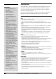
INTRODUCTION FEATURES • 8 Fully programmable zones • Any combination of hardwire or radio zones The E-TECH ET8 is a wholly Australian Designed and Manufactured product from E-Tech Security Products, Australia's largest manufacturer of quality electronic security products. E-Tech Security Products Pty Ltd is a Quality Accredited Company to ISO 9001.
INSTALLATION PROCEDURES The location of the main panel housing should be in an area that is within the protected area of the premises. A linen closet or cupboard are good examples as these are generally located in the centre of the Premises. Positioning of the movement detectors should be considered as the incorrect position may cause unwanted alarms. 2 1 HOW TO REMOVE THE LID 1. Unclip the lid by pushing in the directions of the arrows 1 and 2 as shown below. 2. Remove the Battery from the base. 3.
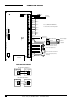
CONNECTION DIAGRAM 2K2 TAMP N.C.
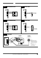
WIRING EXAMPLES EXAMPLE 1 E-TECH QUANTUM DETECTORS 4 WIRE CONNECTION EXAMPLE 3 ANY N.C. DEVICE E-Tech ET8 CONTROL PANEL E-Tech ET8 CONTROL PANEL 0V +12V Zone [1~8] C 0V +12V Zone [1~8] C 2K2 REED SWITCH (N.C. contacts)) 2K2 0V +12V N.C. ALARM N.C. N.C. TAMPER N.C. TAMP C TAMP C E-Tech QUANTUM DETECTOR (all models) EXAMPLE 2 E-TECH QUANTUM DETECTORS 6 WIRE CONNECTION EXAMPLE 4 ANY N.O. DEVICE E-Tech ET8 CONTROL PANEL E-Tech ET8 CONTROL PANEL 2 2K2 0V +12V Zone [1~8] C 0V +12V N.C.
INPUTS MONITORED ZONES The E-Tech ET8 has 10 separate monitored inputs. • 8 x Fully programmable Zone inputs • 2 x 24 hour Tamper input ZONE INPUTS Each zone input must be terminated with a 2K2 (2200 ohm) resistor as supplied. All inputs must be sealed with an EOL resistor even if unused. For wiring details of Keypads, Keyswitches, Panic Buttons and Warning devices, see the wiring diagrams in the wiring section of this manual.
OUTPUTS OUTPUT FUSING The 12V outputs, Siren, Reset and Strobe outputs are protected by Automatic Reset electronic fuses. These outputs will automatically reset once the overload is removed. 12 VOLT OUTPUT: A regulated 13.8 VDC output is available to power detectors and other equipment. This output is available from two sets of terminals marked +12V and 0V. The output is protected by an Automatic Reset fuse. A maximum load of 500mA may be connected to these terminals.
KEYPAD ET8 KEYPAD The ET8 control panel may be supplied with either the LED keypad (100-192) or the E-Tech LCD Keypad (100-667). CABLE LENGTH The maximum allowable cable length is 100m (total cable length to all keypads) . The keypad provides important visual and audible indications and is the main interface for operating and programming the ET8 control panel. DISPLAY TEST (LCD Keyad only) To display all the keypad icons press and hold the button for at least 2 seconds.
OPERATION SUMMARY OPERATION LCD KEYPAD LED KEYPAD RADIO KEY ENTER ARM ARM or... ARM [User Code] [User Code] DISARM ENTER [User Code] ENTER x2 ENTER MONITOR MONITOR MODE or... MONITOR [User Code] PANIC PANIC or... PANIC PANIC [User Code] or... Press twice within 4 seconds P69E 5E must be ON Both keys together ENTER (Keypad Panic Shortcut must be ON, P62E 4E) ENTER [x] [User Code] KEYPAD DURESS ENTER [User Code] PANIC or... [User Code] or... Both keys together or...
PROGRAMMING QUICK START PROGRAMMING Use one of these programming summaries for fast setup of your ET8 as a Local, Audible Monitored or Central Station Monitored system. The control panel will be ready for use immediately. QUICK START 1 - step by step QUICK START 1 LOCAL SYSTEM STEP KEY STROKES 1 1 2 Quick Start 1 shows you how to change User Code 1 (the Master Code). 2 1 1 By default, the dialler is disabled until programmed.
PROGRAMMING FACTORY DEFAULT MASTER CODE: 123 INSTALLER CODE: 000000 PROGRAM MODE LEVELS TABLE 4. FLOW CHART INSTALLER PROGRAM MODE PROGRAM light Installer Program Mode allows access to ALL program options. is FLASHING Power up with Program Link OFF (Usually on first time installation) INSTALLER PROGRAM Mode PROGRAM LIGHT IS FLASHING PROGRAM Note: The panel will remain in Installer Program Mode indefinitely.
PROGRAMMING P01E – P10E RADIO PROGRAMMING P11E – P25E See pages 56,57 USER CODES PROGRAM MODE LEVEL: User codes are the 3 to 6 digit codes used to operate the panel by keypad. User, Installer, Remote by PC User Codes 1–15: Used to arm/disarm the panel. These codes can also be programmed as Arm Only codes. User Code 1 is also the Master Code which is used to access Client Program mode.
PROGRAMMING OPTION No P26E DESCRIPTION DEFAULT P26E Entry Delay Time 1 20 P27E Entry Delay Time 2 6 P28E Exit Delay Time P29E Siren Reset Time NOTE Seconds x10 = 60 seconds 60 Seconds 5 Minutes ENTRY DELAY TIME1 User, Installer, Remote by PC The Entry Delay Time 1 is the time given to Disarm the Panel after a Entry Delay 1 zone is unsecured. FACTORY DEFAULT: The Entry Delay Time1 setting is from 1 to 99 seconds.
PROGRAMMING P30E – P38E VIBRATION SENSITIVITY Installer, Remote by PC Each zone has individually adjustable sensitivity for connection of E-Techensor Vibration Sensors. FACTORY DEFAULT: Zone sensitivity is adjusted by toggling zones ON in options P30E to P38E. PROGRAM MODE LEVEL: Normal sensitivity. P30E, all zones = ON P30E, Normal Sensitivity– vibration analyser disabled. This is used for normal alarm devices. Zone response time, 200ms.
PROGRAMMING ZONE AS SIGNMENT ASSIGNMENT Zones OPTION No DESCRIPTION P39E Double Trigger zones 1 2 3 4 5 6 7 8 P40E Instant zones DELAY GROUP P41E Entry Delay 1 zones Only one option allowed per zone P42E Handover zones P43E Entry Delay 2 zones P44E Lockout zones ON ON ON ON ON ON ON ON P45E Area 1 zones ON ON ON ON ON ON ON ON P46E Area 2 zones P51E Monitor zones P52E 24Hr zones P53E Day zones ON ON ON ON ON ON ON ON ON = Factory default setting P39E DOUBLE TRIGGER ZON
PROGRAMMING P42E HANDOVER ZONES Handover zones are delayed only if entry is made through an Entry Delay zone first. If a Handover zone is triggered first, the zone behaves as an instant zone. Normally, the “point of entry” zone should be Delay zone, with any other zones in the entry path programmed as Handover zones.
PROGRAMMING P51E MONITOR ZONES Monitor zones allow you to Arm selected zones while others are ignored. Typically used for perimeter zones such as windows and doors while you are at home. Example: Upstairs zones are Disarmed while downstairs zones are Armed in Monitor mode.
PROGRAMMING AREA PARTITIONING For example, Office A and Office B operate as separate areas but the entrance foyer used by both offices is assigned to both areas meaning it will automatically Arm when both Areas have Armed. The Common Area then automatically disarms when either Area1 or Area2 Disarms. DEFINITION Area Partitioning allows the 8 zones to be split into two partitions; Area1 and Area2. The panel then effectively operates as two separate systems sharing only the siren outputs and dialler.
P47E P49E DESCRIPTION Codes 1-8 to AREA1 Codes 1-8 to AREA2 OPTION No DESCRIPTION P48E P50E Codes 9-15 to AREA1 Codes 9-15 to AREA2 ON ON ON ON ON ON ON ON ON 1E User Code 2E 9 User Code 3E 10 User Code 4E 11 User Code 5E 12 User Code 6E 13 User Code 7E 14 User Code 15 OPTION No 1E User Code 2E 1 User Code 3E 2 User Code 4E 3 User Code 5E 4 User Code 6E 5 User Code 7E 6 User Code 8E 7 User Code 8 PROGRAMMING ON ON ON ON ON ON ON ON = Factory default setting.
PROGRAMMING ZONE TO OUTPUT MAPPING When a zone alarms, it can turn on any or all of the following 6 outputs: Sonalert, Strobe, Siren, Reset, AUX1, AUX2. The programming is selected with options P54E – P59E. Simply set the zone number to the output to select it. The zone LED will indicate if the zone is selected. The Tamper Input and the Keypad Panic can be programmed to turn on the Reset, Strobe, Sonalert and Siren by using option P61E.
PROGRAMMING P57E PROGRAM MODE LEVEL: SIREN OUTPUT ZONES Selects the zones to trigger the Siren output.
E n tr y b eep s Keysw Monit or/Dis Keysw ar m /A r m / Disar m Tamp er sire n lock out D u res s to R eset o u tp u t Auo E xclud e zo n e s A u to KP dis play o ff Delay AREA 1 -2 o u tp u t s PROGRAMMING OPTION No P60E DESCRIPTION 1E 2E 3E 4E 5E 6E 7E 8E Various options ON ON ON ON = Factory default setting. P60E 1E ENTRY BEEPS The sonalert will beep during Entry Delay.
PROGRAMMING P60E 4E TAMPER ALARM LOCKOUT This option programs the Tamper input to Lockout, i.e. cause the Siren & Reset outputs to sound only once whilst the panel is armed.
Tamp er to Reset outpu Tamp t er to Strob e outp Tamp u er to t Sona ler t Tamp er to Siren outpu KP Pa t nic to Reset KP Pa outpu nic to t Strob e outp KP Pa ut nic to Sona ler t KP Pa nic to Siren outpu t PROGRAMMING OPTION No P61E DESCRIPTION 1E 2E 3E 4E 5E 6E 7E 8E Tamper & Panic alarms mapping ON ON ON ON ON ON ON ON ON = Factory default setting. P61E 1E–4E TAMPER ALARM / OUTPUT MAPPING This option selects which outputs will trigger when a Tamper Alarm occurs.
Shor t cut M emor y Disp Shor t lay cut Z one E xclud Shor t e cut M onitor Shor t Mode cut K eypad Shor t Panic cut A rea1 A Shor t rming cut A rea2 A 2 sec rming Siren Auto Exclu Exit T de ime x 10 PROGRAMMING OPTION No P62E DESCRIPTION 1E 2E 3E 4E 5E 6E 7E 8E Operation Shortcuts, etc ON ON ON ON ON ON = Factory default setting. P62E 1E–6E SYSTEM OPERATION SHORTCUTS Some keypad operations can be programmed to operate with or without a User Code.
Monit or to Reset outpu Monit t or to Strob e outp Monit u or to t Sona ler t o Monit utput or to Siren outpu Day M t ode to R e set ou Day M tput ode to Strob Day M e outp ode to ut Sona Day M ler t o utput ode to Siren outpu t PROGRAMMING OPTION No P63E DESCRIPTION 1E 2E 3E 4E 5E 6E 7E 8E Monitor & Day mode output mapping ON ON ON = Factory default setting. P63E 1E–4E PROGRAM MODE LEVEL: MONITOR MODE OUTPUT MAPPING This option selects which outputs are triggered by alarms in Monitor Mode.
2 sec ond M onitor 2 sec Alarm ond D ay Ala rm Monit or zon es En tr y2 Radio Key c hirp & 50Hz flash mains frequ ency Doub le key Keypa Keypa d Pan ic d Fire Alarm Keypa d Med ical A larm PROGRAMMING OPTION No P64E DESCRIPTION Miscellaneous options 1E 2E 3E 4E 5E 6E 7E 8E ON ON ON ON ON = Factory default setting. P64E 1E 2 SECOND MONITOR MODE ALARM Alarms in Monitor Mode can either activate the programmed outputs for Siren Time duration (P29E) or they can activate the outputs for 2 seconds only.
PROGRAMMING P64E 5E 50Hz MAINS FREQUENCY Selects either 50Hz or 60Hz mains power frequency operation. Leave the factory default for use in Australia and New Zealand. Users in North America should select 60Hz mains frequency. PROGRAM MODE LEVEL: Installer, Remote by PC FACTORY DEFAULT: ON: 50Hz mains frequency Required for the accurate timing of dialler test reports (if programmed). It has no effect on local or other dialler operations.
PROGRAMMING Zones OPTION No P65E DESCRIPTION 1 2 3 4 5 6 7 8 Supervised Radio zones ON = Factory default setting P65E SUPERVISED RADIO ZONES This option assigns zones that will operate as Radio Supervised types. PROGRAM MODE LEVEL: Installer, Remote by PC Supervised signals failure is reported (as per the P66E output options) when no signal is received from a Radio Supervision Zone for the Supervision Time P67E.
Super vision RESE Super T out put vision STRO Super BE ou vision tput SONA Super LERT vision outpu t SIREN Super o u t p vision ut AUX1 Super outpu vision t AUX2 Super outpu vision t speed Super up x6 vision speed up x1 0 PROGRAMMING OPTION No P66E DESCRIPTION 1E 2E 3E 4E 5E 6E 7E 8E Radio Supervision Alerts ON = Factory default setting. P66E 1E RADIO SUPERVISION ALERTS – RESET OUTPUT Setting this option turns the Reset output ON when a SUPERVISED RADIO alert occurs.
PROGRAMMING P66E 4E RADIO SUPERVISION ALERTS – SIREN OUTPUT Setting this option turns the Siren output ON when a SUPERVISED RADIO alert occurs. The Siren output will remain ON for the duration of the ALARM TIME (Set by Option P29E).
3K3 z one r esisto rs Radio Key P anic t oggle Radio s AUX Key P 1 anic p Radio ulses AUX1 Key A rming 24hr unsea zone led w fire sir arning en so 4th b und utton Radio Key fo Quiet r AUX chirps 1 on Ar m/Dis arm PROGRAMMING OPTION No P68E DESCRIPTION 1E 2E 3E 4E 5E 6E 7E 8E Miscellaneous options ON = Factory default setting. P67E SUPERVISION TIME, page 31 P68E 2E 3K3 ZONE RESISTORS Setting this option ON changes the Zone 1 to Zone 8 (and External Tamper) monitoring resistor from 2K2 to 3K3.
PROGRAMMING P68E 5E RADIO KEY ARMING, UNSEALED ZONE WARNING Setting this option ON allows a 2 second SIREN warning if there is an unsealed zone in an Area Armed by a Radio Key.
OPTION No P69E DESCRIPTION . ARM1 pulse outpu ARM2 t pulse outpu Quiet t Monit or sir en 6 bee ps on Armin g Radio Key M onitor . Armin g . PROGRAMMING 1E 2E 3E 4E 5E 6E 7E 8E Miscellaneous options 2 ON = Factory default setting. P69E 1E ARM1 PULSE OUTPUT Installer, Remote by PC This option selects the ARM1 output to pulse on for 2 seconds whenever arming or disarming of Area1. FACTORY DEFAULT: (The ARM1 output normally toggles when arming/disarming).
PROGRAMMING P69E 4E 6 BEEPS ON ARMING Normally the keypad/s onboard SONALERT gives 3 beeps when the ET8 is Armed. Turning this option ON will give 6 keypad beeps when Arming.
PROGRAMMING OPTION No DESCRIPTION FACTORY DEFAULT Telephone Number 1 - Primary Telephone Number 2 - Secondary Telephone Number 3 - Test Calls Telephone Number 4 - Callback for Up/download Follow Me Telephone Number - For Audible Dialling none none none none none DESCRIPTION FACTORY DEFAULT P72E Account Number 1 0000 P73E Account Number 2 0000 P70E P71E P80E P81E P00E OPTION No P70E, P71E TELEPHONE NUMBERS 1 & 2 The ET8 can dial up to 2 phone numbers when an event is to be transmitted to a rem
PROGRAMMING P80E TELEPHONE NUMBER 3 – TEST CALLS Phone Number 3 is used to send Test Calls. If it is not programmed then Test Calls are sent using Telephone No 1 & 2.
PROGRAMMING Zones OPTION No DESCRIPTION 1 P74E Report zone alarms ON ON ON ON ON ON ON ON 2 3 4 5 6 7 8 P76E Report zone restorals ON ON ON ON ON ON ON ON P78E Multiple zone alarms P79E Account No.2 zones ON = Factory default setting P74E REPORT ZONE ALARMS This option selects which zone inputs will send Alarm reports to the Central Station.
P75E P77E Report Misc. Alarms 1~8 ON ON ON ON Report Misc. Restorals 1~8 ON ON ON ON ON ON ON ON P92E P93E 8E DESCRIPTION 1E R adio Tamp er 2E R adio Panic 3E R adio Batte ry 4E S uper visio n Fa 5E P il anel Batte ry 6E M ains Fail 7E OPTION No 1E D ures s 2E M edica l 3E K /P & K/S P anic 4E F ire 5E P anel Tamp er 6E E xtern al Ta m 7E K per eypa d Tam per 8E E xit In stall mod e PROGRAMMING Report Misc. Alarms 9~14 ON ON ON ON Report Misc.
PROGRAMMING OPTION No P83E DESCRIPTION P83E Test Call Interval P84E Time Before Next Test Call DEFAULT NOTE 84 x2 = 168hrs (7 days) 6 x2 = 12hrs TEST CALL INTERVAL Test calls to the Central Station can be sent at intervals between 2 and 198 hours in 2 hour increments. PROGRAM MODE LEVEL: Installer, Remote by PC 84 (=168hrs =7 days) Programmable from 2 to 198 Hours. Enter a value between 1 and 99. (This is automatically multiplied by 2). NOTES: Test Calls must be enabled by option P89E 1E.
Disab le dia ller Conta ct ID forma t Audib le DT MF fo rmat Audib le PU LSE f o rmat Conta ct ID + Au dible Conta DTMF ct ID + Au dible . PULS E . PROGRAMMING OPTION No P86E DESCRIPTION Reporting Formats 1E 2E 3E 4E 5E 6E 7E 8E ON ON = Factory default setting. P86E 1E DISABLE DIALLER Installer, Remote by PC This option disables the dialler even if telephone numbers and other dialler options are programmed. FACTORY DEFAULT: Up download or remote telephone access remain enabled.
PROGRAMMING P86E 5E CONTACT ID + AUDIBLE DTMF FORMAT For simultaneous Central Station and Audible Monitoring. PROGRAM MODE LEVEL: Installer, Remote by PC The alarm message will be sent to the Central Station on the Primary telephone number and then in audible DTMF format to the Follow Me telephone number.
OPTION No P87E DESCRIPTION Miscellaneous Dialling Options . . . 4 diall ing at tempt s . Split d ial Ph one N os. Chec k for dial to ne . PROGRAMMING 1E 2E 3E 4E 5E 6E 7E 8E ON ON ON = Factory default setting. P87E 1E SPLIT DIAL PRIMARY/SECONDARY PHONE NUMBERS This option selects the order in which Telephone numbers 1 & 2 are dialled.
AREA 1 Ope n/Clo se rep AREA or t 2 Ope n/Clo se rep Chirp or t Siren on kis s-off Flash Strob e on k iss-of Force f d Ope ning r epor t Delay Closin g rep or t Manu al Exc lude r epor t Auto Exclu de rep or t PROGRAMMING OPTION No P88E DESCRIPTION 1E 2E 3E 4E 5E 6E 7E 8E Open/Close reporting options ON ON ON ON = Factory default setting. P88E 1E PROGRAM MODE LEVEL: Installer, Remote by PC FACTORY DEFAULT: AREA1 OPEN/CLOSE REPORTS Enables or disables sending of AREA1 Open/Close reports.
PROGRAMMING P88E 5E FORCED OPENING REPORT If Forced Opening Report is selected ON – when an alarm has been reset by a valid User Code (or Radio Key), the dialler will send an Opening report along with a restoral report for the zone or miscellaneous input which caused the alarm.
OPTION No P89E . Enable Test C alls Mains Repo r t dela Listen y -in to dialle r Swing er shu tdown Line F ault M onitor Line F ault to AUX2 . PROGRAMMING DESCRIPTION 1E 2E 3E 4E 5E 6E 7E 8E Miscellaneous Reporting options ON ON ON ON = Factory default setting. P89E 1E PROGRAM MODE LEVEL: ENABLE TEST CALLS This option enables the reporting of dialler test calls to the Central station.
PROGRAMMING P89E 4E SWINGER SHUTDOWN Installer, Remote by PC Limits the number of calls made by a zone alarm when Multiple Zone Alarms are enabled for that zone. FACTORY DEFAULT: If enabled, multiple reports are limited to three per zone. PROGRAM MODE LEVEL: ON: Swinger Shutdown enabled PROGRAMMING SEQUENCE: NOTES: • This prevents unnecessary multiple alarms reported to the Central station in cases, for example, where a door is ‘swinging’ in the wind.
Uploa d/Dow nload Direc t Con nect Remo te Arm ing Remo te Dis armin g Remo te AU X con trol Remo te Sta tus re por tin Remo g te Eve nt rep or ting Callba ck mo de PROGRAMMING OPTION No P90E DESCRIPTION 1E 2E 3E 4E 5E 6E 7E 8E Upload/Download options ON = Factory default setting.
PROGRAMMING P90E 4E PROGRAM MODE LEVEL: Installer, Remote by PC FACTORY DEFAULT: OFF: No Remote Disarming NOTES: REMOTE DISARMING Allows the remote Disarming of the control panel using a standard DTMF telephone (or mobile phone) from anywhere in the world.
PROGRAMMING OPTION No P91E P91E DESCRIPTION Required Rings to answer DEFAULT NOTE 1 REQUIRED RINGS Installer, Remote by PC Sets the number of double-rings before an incoming call is answered. This is used for Remote Access. FACTORY DEFAULT: Programmable from 1 to 16 rings. Enter a value between 1 and 16. PROGRAM MODE LEVEL: 1 See below for a detailed description.
PROGRAMMING OPTION No These options allow selective restoring of various factory defaults. For example, you can default (clear) all the User Codes, without affecting any other programmed options.
E-TECH RADIO RADIO QUICK START PROGRAMMING RADIO KEYS: Select which User Codes 2–8 will be Radio Codes (P09E–P10E) Select the User Code (P12E–P25E) Press 1E The READY light will turn ON to indicate that the User Code is ready to accept the Radio Key Press the OFF button on the Radio Key to be programmed If the Radio Key is accepted, the READY light will turn off and 3 beeps will sound PROGRAMMING RADIO DEVICES (Radio PIRs etc): Select a zone to which the Radio PIR will be assigned (P01E–P0
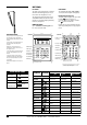
E-TECH RADIO DEVICES Signal types transmitted ON OF F E-TECH RADIO PANIC RADIO KEY 3 BUTTON RADIO PIR RADIO REED SWITCH RADIO SMOKE DETECTOR 100-665 100-664 100-663 100-662 100-203 ON button ON button yes yes yes OFF button yes yes yes yes yes SIGNAL TYPE RADIO KEY PENDANT ALARM RESTORAL LOWBA TT yes TAMPER SUPERVISION yes yes yes yes yes yes yes RADIO DEVICES – OPERATION ALARM: Any E-Tech Radio Device can operate on any zone 1–8 as programmed by P01E~P08E.
E-TECH RADIO P01E ~ P08E RADIO DEVICE PROGRAMMING Each of the 8 zones of the ET8 can be a radio zone. Once programmed, zones can accept both Radio Devices and normal zone inputs simultaneously. PROGRAM MODE LEVEL: Installer, Remote by PC The optional 100–200 E-Tech Radio Interface is required for Radio Devices to operate. FACTORY DEFAULT: No Radio Devices programmed NOTES: A Radio Device is any type of E-Tech transmitter including Radio PIR, Radio Reed Switches, Radio Smoke Detector.
E-TECH RADIO P09E, P10E RADIO CODES Each of the 15 User Codes, except for the Master Code, can be programmed to be Radio Codes. This allows up to 14 E-Tech Radio Keys to be used for Arming and Disarming of the panel. The optional 100–200 E-Tech Radio Interface is required for Radio Keys to operate. PROGRAM MODE LEVEL: Installer, Remote by PC FACTORY DEFAULT: No Radio Codes PROGRAMMING RADIO KEYS NOTES: • All User Codes can be Radio Codes except User Code 1 (Master Code) which is always a Keypad Code.
CENTRAL STATION MONITORING The ET8 control panel has an on-board digital dialler which can send detailed alarm messages to a Central Monitoring Station. CENTRAL STATION MONITORING MONITORED PREMISES TELEPHONE LINE MONITORING STATION The digital messages can include information about the zone/s which caused the alarm, tamper alarms, low battery or mains failure reports, and it can also (by user number) identify the users who Arm and Disarm the system.
OPERATING THE ET8 BY TELEPHONE AUDIBLE FEEDBACK 3 BEEPS: • The User Code is valid • Successful Arming or Disarming • An Auxiliary output has been turned ON. 1 LONG BEEP: • ET8 is already Armed • Invalid code. Try again. 1 SHORT BEEP: • An Auxiliary output has been turned OFF. The ET8 will allow a user to call in to the panel, using a standard DTMF telephone, and remotely Arm or Disarm all areas and also turn on or off Aux 1 and Aux 2. SEQUENCE OF OPERATION.
E-TECH ACCESSORIES MOTION DETECTORS E-Tech manufactures a range of high quality and efficient motion detectors - including passive infra-red detectors, dual technology / microwave and infra-red devices as well as ceiling mounted 360° detectors. 100-021 Quantum 100-226 Quantum Plus 100-210 Quantum Dual 100-048 Quantum 360 All E-Tech detectors are designed using the most modern technology and techniques that ensure superior reliability and performance.
WIRELESS PRODUCTS RADIO ACCESSORIES Ask your installer about the range of E-Tech radio devices for the optional extra convenience of wireless remote control and wireless detection. Operating your E-Tech security system can be as convenient as opening your car door. The E-Tech Radio Key™ provides the benefits of separate ON, OFF and PANIC buttons in a slim, waterproof remote control. * E-Tech radio products require a E-Tech Radio Interface (100-200) to be fitted to the control panel.
PROGRAMMING OPTIONS SUMMARY OPTION DESCRIPTION DEFAULT P00E Follow Me Tel. No.
INSTALLATION RECORD Date purchased: Date installed: Installation Company: Telephone: E-TECH ET8 ALARM CONTROL PANEL Monitoring Company: ZONES DEVICE TYPE PIR, Reed switch, etc DESCRIPTION P74E Report (dialler) P57E SIREN OUTPUT P56E SONALERT OUTPUT P54E RESET OUTPUT P52E 24 HOUR Minutes P51E MONITOR P29E SIREN RESET TIME P46E AREA 2 Seconds P45E AREA 1 P28E EXIT DELAY TIME P40E INSTANT Seconds P42E HANDOVER P27E ENTRY DELAY TIME 2 ZONE ASSIGNMENT P43E ENTRY DELAY 2 Seconds P41E E