E-TON Vector 250R OWNER’S MANUAL
Important Notices READ and UNDERSTAND this owner’s manual Both the operator and the adult supervisor should completely read and understand this owner’s manual before operating this vehicle. This owner’s manual will instruct you in the safe operation of the vehicle. NO Passengers This vehicle was designed for operation ONLY by the operator, (Driver). The load limit and seat configuration is designed for the operator ONLY. It is not safe to carry passengers on the vehicle.
Table of Contents Important Notices.................................................................................................................................... 1 Safety Notes ............................................................................................................................................ 4 Additional safety tips: ............................................................................................................................. 7 Vehicle Identification Numbers....
Table of Contents Maintenance Schedule .......................................................................................................................... 26 Owners Maintenance Records .............................................................................................................. 26 Warranty ............................................................................................................................................... 27 Warranty .........................................
Safety Notes 1. Both the adult supervisor and youth operator must fully understand everything in this manual before operating this vehicle. 2. This vehicle was designed for the operator only. NO PASSENGERS should be allowed on this vehicle. 3. This vehicle is designed for operation on level, obstacle free off-road areas. 4. Riding this vehicle on public roads or highways is illegal. If it becomes necessary to cross a public road or highway, the vehicle should be pushed across using extreme caution. 5.
10. NEVER ride this vehicle unless it has been properly maintained and adjusted. Always perform a pre-ride inspection of your vehicle. Look for wires, bolts and other fasteners that may have come loose on previous rides. Inspect the drive chain, throttle and brakes for proper adjustment and operation. Check the engine oil level in the oil tank. Check fuel level and inspect for fuel leaks. (Remember, you can ride further in 1 hour than you can walk back in 1 day!) 11.
13. NEVER REFUEL this vehicle when hot. Ask your adult supervisor to refuel your vehicle. Gasoline is extremely flammable and will ignite if spilled on a hot engine or muffler. Never smoke or expose the fuel to an open flame or spark while refueling your vehicle. Always refuel your vehicle in a safe place free of any ignition source. 14. NEVER run the vehicle in an enclosed area.
Additional safety tips: • • • • • • • • • • • • • • • • • • • • • • • • • • • Participate in an approved ATV safety education training program Always provide responsible adult supervision for ATV operators younger than 18 years of age Don't let youngsters ride full-sized ATV's Follow all safety recommendations of the ATV manufacturer Operate ATVs only during daylight Wear a helmet with face protection at all times Operate only four-wheeled ATVs Provide a drug and alcohol free environment Always use the b
Vehicle Identification Numbers Your VIN RFZ______________ Eng. No._______________ Vehicle Identification Number (VIN) is located at the front of the unit under the front fender on a plate mounted between the main frame rails. Engine serial number is located on the left-hand side of the engine on the crankcase housing. Controls, Switches & Feature Locations Locations of controls and features 1. 2. 3. 4. 5. 6.
Control Features Engine Stop Switch Throttle lever The stop switch is a red colored rocker switch located on the left-hand handle bar. To start and run the engine, this switch must be placed in the on, “Ω”, position. The throttle lever is located on the right-hand handle bar below the grip. To operate the throttle lever, place your right thumb on the lever and press forward to increase your speed.
The throttle cable should be adjusted so there is 2mm, (1/8”) free travel at the lever before the throttle starts to open. Front and Rear Brakes This vehicle is equipped with dual front hydraulic Disc brakes and a rear hydraulic disc brake Fuel Tank The front brakes are controlled by the long brake lever on the right-handle bar. The rear brake is controlled by foot peddle located in the right foot well of the unit. The rear brake is the primary stopping brake on your vehicle.
Tighten the cap snugly, being careful not to over tighten. Over tightening the cap can cause damage to the cap or seal. The fuel tank capacity is 12 liters, 3.17 gal, including a reserve of 2.5 liters, 0.66 gal. Use unleaded automobile gasoline with an octane level of 89 or higher. NEVER REFUEL YOUR ATV when the engine is HOT. Wait 30 minutes after turning off the unit before refueling. Spilling fuel on a HOT engine could cause a fire. Wipe up any fuel spills before re-starting.
turning the bowl counter clockwise. Remove the old filter by pulling down on the filter to disengage the pressure fitting from the mount. Install the new filter by pressing up until the filter snaps in place over the mount and re install the filter bowl by turning clockwise until it is hand tight. Turn the fuel valve to the “PRI’ position to fill the filter bowl with fuel and check for leaks. Return the fuel valve to the normal “ON” operating position.
Changing the engine oil The engine oil requires changing every 1800Mi / 3000KM and at the start of each riding season to protect the engine. The following steps should be followed when changing the engine oil. 1. Place a oil catch pan directly below the engine crankcase. 2. Remove the crankcase drain plug located on the bottom of the crankcase on the underside of the unit. 3. Remove the engine oil dipstick located on the right hand side of the crankcase directly below the transmission shift lever. 4.
Removing the radiator cap while the coolant system is hot can cause over boiling and serious burns or other injuries season for signs of deterioration such as cracking of checking of the hose surface. Replace cooling system hoses at least every 3 years. Transmission Engine Coolant Mixture The engine coolant should be a mixture of distilled water and anti-freeze solution with a specification rating of H68. The following chart will help you determine the correct water to anti-freeze ratio.
lightly apply pressure to the throttle until you feel the unit shift and the indicator light confirms the shift has been completed. If the brakes are not fully applied while shifting the transmission the engine will stop running. Transmission Oil every 3000Km/ 1800 Mi or at the beginning of each riding season which ever come first. The following steps should be followed when changing the transmission oil. 1. Place a oil catch pan directly below the transmission case. 2.
Replace any tire or wheel found to be damaged. Operating your ATV with damaged tires or wheels is dangerous. Damaged tires or wheels can result in a sudden loss of tire pressure and control which could result in injuries. Check your tire pressure before each riding session and at each refueling operation. Always check the pressure when the tires are cool. Use the tire pressure gauge that came with your ATV to check the tire pressure. Tire Pressure Recommended tire pressures are: Min 3.2psi / 0.
5. Soak the element in clean engine oil until completely saturated. 6. Squeeze out the excess oil until the element does not drip any oil. 7. Allow the element to dry then reinstall the element and cover. Braking Systems Your ATV unit is equipped with dual front hydraulic disc brakes and a single rear hydraulic disc brake.
Brake fluid Dot-3 SAE-J1703 grade. Inspect brake line joints and wheel cylinders for leaks and repair as needed. Rear Brake System Inspection Apply the brakes by squeezing the brake lever. The level should stop with the brakes fully apply and at least ½” / 13mm of clearance between the brake lever and the handle bar grip. It there is less than ½” / 13mm clearance or the lever is not firm the brake pads may require changing. Or the line may need bleeding.
Purging Brake Lines For the hydraulic brake system to operate safely, the brake system must be purged of air in the lines and reservoir. To After riding your unit, be sure to clean any build up of mud, sand and dirt from the brake rotor skid plate. This will protect the rotor disc from rust and corrosion. To Fill the Reservoir Remove the reservoir cover by removing the two cover bolts. Fill the reservoir to 1/8” from top with Dot-3 SAEJ1703 grade brake fluid.
Drive Chain The drive chain will stretch with use and will require periodic adjustments. To check the chain tension, remove the chain guard and measure the slack. The amount of slack in the chain should not exceed 10-20mm or ¼” - ½”. Inspect the drive and axle sprockets for worn, damaged or broken teeth. Replace as needed. Inspect the chain links for damaged, worn or loose rivets. Repair or replace as needed. hours of operation, or more frequently if needed, with a high quality chain lubricant.
The cable should be adjusted to allow for ⅛” free travel before the throttle engages the carburetor throttle slide. To adjust the cable’s free travel, loosen the locking nut of the cable adjuster, and turn the adjuster wheel until there is ⅛” free travel When reinstalling the battery, be sure to connect the red cable to the positive (+) terminal and the black cable to the negative (-) terminal. The battery should be replaced every three years or when it no longer holds a charge. in the lever.
Digital Console The Vector 250 is equipped with a digital console which displays information about the operating conditions of your ATV. 1. For the first two weeks of operation do not run your ATV at full throttle for extended periods of time. 2. Your first tank of fuel should be a premixture of fuel and oil at a 50:1 ratio. This will insure that the oil pump system has been primed and bled of air that may have occurred in shipping. 3. Do not operate the unit at more than 85% of maximum speed. 4.
Park the unit on a level surface and lock the parking brake. Place the transmission gear selector switch in the “N”, Neutral, position. Insert the key into the ignition switch and turn to the “ON” position. Turn the engine stop switch to the “ON” position. Set the manual choke lever to the full left position (Choke close or on) Apply front or rear brakes. Apply slight pressure to the throttle lever. Press the starter button on the left-handle bar.
Vector 250R Specifications Engine Type Displacement Bore / Stroke Compression Ratio / Pressure Torque / BHP Four cycle , Single Cylinder, Liquid cooled 249cc φ71mm * 63mm 10.6 : 1 22.3Nm @ 5500rpm / 16.4bhp Meet or exceeds EPA clean air requirements/CA Green Sticker Electrical starter EPA Approved Starting Transmission Type Automatic (C.V.T. V-Belt) Manual Shift Fwr/Rev Chassis Overall Length Overall Width Overall High Wheel Base Seat Height Ground Clearance Dry Weight 1780mm / 70.1" 1030mm / 40.
Sprockets Front Rear Chain 520x15t 520x38t #520*90 O-Ring Battery Jell Acid (Maintenance Free) 12V-9AH - GTX12-BS Fluids Type Volume Type Volume Type Volume Fuel Engine Oil Transmission Unleaded Gasoline 89 octane 12liters / 3.17gal SAE 10-30W 1.4liters / 1.4gt (1.2liters / 1.2qt for change) SAE 85/140 weight gear Oil 750cc / 25.4oz (650cc / 22oz for change) Spark Plug NGK NGK-CR8E Electrode Gap 0.6-0.7mm / 0.
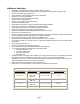
Maintenance Vector 250R Schedule Pre-Ride Safety Inspection 300Km 200Mi 1 Month 1000Km 600Mi 3 Months Fuel Lines I Throttle Operation I I Air Filter I C 3000Km 1800Mi 6 Months 6000Km 3500Mi 12000Km 7500Mi 1 Year 2 Years I Notes: R R Fuel Filter R Spark Plug I I Drive Chain I,L Brake Pads I I Brake System I I Brake Fliud I Bolts, Nuts, & Fastners I I Wheels & Tires I I Steering System I Suspension System I R Lubricate every month R I I I I I C.V.T.
Vector 250R Wire diagram Page 27
Warranty ETON AMERICA, LLC. LIMITED VEHICLE WARRANTY ETON America warrants all new ETON vehicles sold by authorized Eton Dealers to be free from defects in materials and workmanship, subject to the following exclusions and limitations. New vehicles sold by an authorized dealer to original retail consumers are covered by this policy for a period of six (6) months from the date of delivery. There is no mileage limitation.
ETON AMERICA, LLC. LIMITED VEHICLE WARRANTY Scheduled maintenance service is the responsibility of the owner during and after the warranty period. In the event of a failure or required repair, the owner should take vehicle to an authorized dealer for repair without undue delay and within a maximum of thirty, (30), days of the occurrence of the problem. All eligible warranty repairs must be made at any authorized dealer’s normal place of business.
Owner’s Notes: Page 30
Page 31