Elekt ro -Automatik Betriebsanleitung PS 5000 A DC Laboratory Power Supply Doc ID: PS5DE Revision: 05 Date: 01/2017
PS 5000 A Serie INHALT 1 ALLGEMEINES 1.1 1.1.1 1.1.2 1.1.3 1.1.4 1.2 1.3 1.4 1.5 1.6 1.7 1.7.1 1.7.2 1.7.3 1.7.4 1.7.5 1.8 1.8.1 1.8.2 1.8.3 1.8.4 1.9 1.9.1 1.9.2 1.9.3 1.9.4 1.9.5 1.9.6 2 Zu diesem Dokument.....................................4 Aufbewahrung und Verwendung....................4 Urheberschutz (Copyright).............................4 Geltungsbereich..............................................4 Symbole und Hinweise...................................4 Gewährleistung und Garantie.........
PS 5000 A Serie 1. Allgemeines 1.1 Zu diesem Dokument 1.1.1 Aufbewahrung und Verwendung Dieses Dokument ist für den späteren Gebrauch und stets in der Nähe des Gerätes aufzubewahren und dient zur Erläuterung des Gebrauchs des Gerätes. Bei Standortveränderung und/oder Benutzerwechsel ist dieses Dokument mitzuliefern und bestimmungsgemäß anzubringen bzw. zu lagern. 1.1.
PS 5000 A Serie 1.4 Entsorgung des Gerätes 1.5 Produktschlüssel Ein Gerät, das zur Entsorgung vorgesehen ist, muß laut europaweit geltenden Gesetzen und Verordnungen (ElektroG, WEEE) vom Hersteller zurückgenommen und entsorgt werden, sofern der Betreiber des Gerätes oder ein von ihm Beauftragter das nicht selbst erledigt.
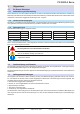
PS 5000 A Serie 1.7 Sicherheit 1.7.1 Sicherheitshinweise Lebensgefahr - Gefährliche Spannung • Beim Betrieb elektrischer Geräte stehen zwangsweise bestimmte Teile unter teils gefährlicher Spannung, mit Ausnahme der 40 V-Modelle gemäß SELV.
PS 5000 A Serie 1.7.2 Verantwortung des Bedieners Das Gerät ist für den gewerblichen Einsatz bestimmt. Das Personal unterliegt daher den gesetzlichen Pflichten zur Arbeitssicherheit. Neben den Warn- und Sicherheitshinweisen in dieser Anleitung müssen die für den Einsatzbereich gültigen Sicherheits-, Unfallverhütungs- und Umweltschutzvorschriften eingehalten werden. Insbesondere gilt, daß die das Gerät bedienenden Personen: • sich über die geltenden Arbeitsschutzbestimmungen informieren.
PS 5000 A Serie 1.7.5 Alarmsignale Das Gerät bietet eine Signalisierung von Alarmsituationen, jedoch nicht von Gefahrensituationen. Die Signalisierung erfolgt optisch auf der Anzeige als Text. Alle diese Alarme bewirken die dauerhafte oder zeitweise Abschaltung des DC-Ausgangs.
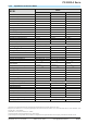
PS 5000 A Serie 1.8.3 Spezifische technische Daten Modell 160 W PS 5040-10 A PS 5080-05 A PS 5200-02 A Netzspannung 90...264 V AC 90...264 V AC 90...264 V AC Netzanschluß 1ph,N,PE 1ph,N,PE 1ph,N,PE Netzfrequenz 50/60 Hz 50/60 Hz 50/60 Hz Netzsicherung (intern) MT 4 A MT 4 A MT 4 A Ableitstrom < 3.5 mA < 3.5 mA < 3.5 mA Leistungsfaktor ~ 0.99 ~ 0.99 ~ 0.
PS 5000 A Serie 160 W Modell PS 5040-10 A PS 5080-05 A PS 5200-02 A Isolation Ausgang (DC) zu Gehäuse (PE) Eingang (AC) zu Ausgang (DC) DC-Minus: dauerhaft max. ±200 V DC-Plus: dauerhaft max. ±200 V + Ausgangsspannung Max. 2500 V, kurzzeitig Verschiedenes Kühlungsart Natürliche Konvektion (Standardrichtung: seitlich rein, hinten raus) Umgebungstemperatur 0..50°C Lagertemperatur -20...
PS 5000 A Serie Modell 320 W PS 5040-20 A PS 5080-10 A PS 5200-04 A Netzspannung 90...264 V AC 90...264 V AC 90...264 V AC Netzanschluß 1ph,N,PE 1ph,N,PE 1ph,N,PE Netzfrequenz 50/60 Hz 50/60 Hz 50/60 Hz Netzsicherung (intern) MT 4 A MT 4 A MT 4 A Ableitstrom < 3.5 mA < 3.5 mA < 3.5 mA Leistungsfaktor ~ 0.99 ~ 0.99 ~ 0.99 Maximale Spannung UNenn 40 V 80 V 200 V Maximaler Strom INenn 20 A 10 A 4A Maximale Leistung PNenn 320 W 320 W 320 W Überspannungsschutzbereich 0..
PS 5000 A Serie 320 W Modell PS 5040-20 A PS 5080-10 A PS 5200-04 A Isolation Ausgang (DC) zu Gehäuse (PE) Eingang (AC) zu Ausgang (DC) DC-Minus: dauerhaft max. ±200 V DC-Plus: dauerhaft max. ±200 V + Ausgangsspannung Max. 2500 V, kurzzeitig Verschiedenes Kühlungsart Temperaturgeregelter Lüfter, Lufteinlaß seitlich, Luftauslaß hinten Umgebungstemperatur 0..50°C Lagertemperatur -20...
PS 5000 A Serie Modell 640 W PS 5040-40 A PS 5080-20 A PS 5200-10 A Netzspannung 90...264 V AC 90...264 V AC 90...264 V AC - mit zusätzlichem Derating 90...150 V AC 90...150 V AC 90...
PS 5000 A Serie 640 W Modell PS 5040-40 A PS 5080-20 A PS 5200-10 A Isolation Ausgang (DC) zu Gehäuse (PE) Eingang (AC) zu Ausgang (DC) DC-Minus: dauerhaft max. ±200 V DC-Plus: dauerhaft max. ±200 V + Ausgangsspannung Max. 2500 V, kurzzeitig Verschiedenes Kühlungsart Temperaturgeregelter Lüfter, Lufteinlaß seitlich, Luftauslaß hinten Umgebungstemperatur 0..50°C Lagertemperatur -20...
PS 5000 A Serie 1.8.4 Ansichten Bild 1 - Vorderseite Bild 2 - Rückseite A - Netzschalter B - Bedienteil C - DC-Ausgang D - Schraubklemme mit Hilfsausgang und Fernfühlung E - Steuerungsschnittstelle USB F - Lüftungsaustritt G - Netzanschluß mit Netzsicherung EA Elektro-Automatik GmbH Helmholtzstr. 31-33 • 41747 Viersen Telefon: 02162 / 3785-0 Telefax: 02162 / 16230 www.elektroautomatik.de ea1974@elektroautomatik.
Bild 3 - Seiteansicht von rechts, 640 W-Ausführung Bild 4 - Seitenansicht von rechts, 160 W / 320 W-Ausführung PS 5000 A Serie EA Elektro-Automatik GmbH Helmholtzstr. 31-33 • 41747 Viersen Telefon: 02162 / 3785-0 Telefax: 02162 / 16230 www.elektroautomatik.de ea1974@elektroautomatik.
PS 5000 A Serie Bild 5 - Bedienfeld Übersicht der Bedienelemente am Bedienfeld Für eine genaue Erläuterung siehe Abschnitt „1.9.4. Die Bedieneinheit (HMI)“. (1) Anzeige Dient zur Anzeige von Sollwerten, Istwerten und Status. Tastenfeld (5 Tasten) Taste Recall: Abrufen der gespeicherten Sollwertsätze (siehe 3.4.6) Taste OVP/OCP: Umschaltung auf Anzeige und Einstellmodus für OVP-, OCP- und OPP-Werte (2) Taste Local: Aktivierung / Deaktivierung der Fernsteuerungssperre (siehe 3.5.
PS 5000 A Serie 1.9 Aufbau und Funktion 1.9.1 Allgemeine Beschreibung Die elektronischen DC-Labornetzgeräte der Serie PS 5000 A sind durch ihre recht kompakten Tischgehäuse besonders für den Einsatz in Laboren, Werkstätten, Schulen und andere Ausbildungseinrichtungen geeignet, wo variable Spannungen und kleine Leistungen gebraucht werden. Für die Fernsteuerung per PC oder SPS verfügt das Gerät serienmäßig über eine rückwärtige USB-Schnittstelle.
PS 5000 A Serie 1.9.4 Die Bedieneinheit (HMI) HMI steht für Human Machine Interface, auf deutsch Mensch-Maschine-Schnittstelle, und besteht hier aus einer Anzeige, zwei Drehknöpfen mit Tastfunktion und fünf Tasten. 1.9.4.
PS 5000 A Serie 1.9.4.2 Drehknöpfe Solange das Gerät manuell bedient wird, dienen die beiden Drehknöpfe zur Einstellung aller Sollwerte. Für eine genauere Erläuterung der einzelnen Funktionen siehe „3.4. Manuelle Bedienung“. Beide Drehknöpfe haben noch eine zusätzliche Tastfunktion, die zwischen Grob- und Feineinstellung (Anzeige: Fine) umschaltet. Dabei gibt es keine Trennung zwischen den beiden Knöpfen.
PS 5000 A Serie 2. Installation & Inbetriebnahme 2.1 Lagerung 2.1.1 Verpackung Es wird empfohlen, die komplette Transportverpackung (Lieferverpackung) für die Lebensdauer des Gerätes aufzubewahren, um sie für den späteren Transport des Gerätes an einen anderen Standort oder Einsendung des Gerätes an den Hersteller zwecks Reparatur wiederverwenden zu können. Im anderen Fall ist die Verpackung umweltgerecht zu entsorgen. 2.1.
PS 5000 A Serie 2.3.3 Anschließen an das Stromnetz (AC) • Das Anschließen des Gerätes mittels des mitgelieferten Netzkabels kann an jeder Wandsteckdose bzw. Steckdosenverteilung erfolgen, die über einen Schutzkontakt verfügt • Bei Verwendung einer Steckdosenverteilung muß die Gesamtleistung aller angeschlossenen Geräte beachtet werden, so daß der Maximalstrom (Leistung ÷ Minimalspannung) nicht den für die Steckdosenverteilung und der Hauptanschlußsteckdose definierten max.
PS 5000 A Serie 2.3.5 Erdung des DC-Ausgangs Grundsätzlich können einzeln betriebene Geräte entweder am DC-Minuspol oder DC-Pluspol geerdet, sprich direkt mit PE verbunden werden. Bei Reihenschaltung hingegen gibt es zusätzliche Einschränkungen, weil bei Erdung des Pluspols ein oder mehrere DC-Minuspole im Potential negativ verschoben werden. Hierbei darf kein DC-Minuspol mehr als 200 V Differenz zu PE haben. Im Fall, daß es erforderlich ist, den DC-Plusausgang zu erden ergibt sich z. B.
PS 5000 A Serie Bild 7 - Beispiel Fernfühlungsverdrahtung bei Nutzung des Hauptausgangs 2.3.7 Anschließen des USB-Ports Um das Gerät über diesen Anschluß fernsteuern zu können, verbinden Sie Gerät und PC über das mitgelieferte USB-Kabel und schalten Sie das Gerät ein, falls noch ausgeschaltet. 2.3.7.1 Treiberinstallation (Windows) Bei der allerersten Verbindung mit dem PC sollte das Betriebssystem das Gerät als neu erkennen und einen Treiber installieren wollen.
PS 5000 A Serie 2.3.8 Erstinbetriebnahme Bei der allerersten Inbetriebnahme nach dem Erwerb des Gerätes und der Erstinstallation sind zusätzliche Maßnahmen zu ergreifen: • Überprüfen Sie die von Ihnen verwendeten Anschlußkabel für DC auf ausreichenden Querschnitt! • Überprüfen Sie die werkseitigen Einstellungen bezüglich Sollwerte, Sicherheits- und Überwachungsfunktionen daraufhin, daß Sie für Ihre Anwendung passen und stellen Sie sie ggf.
PS 5000 A Serie 3. Bedienung und Verwendung 3.1 Personenschutz • Um Sicherheit bei der Benutzung des Gerätes zu gewährleisten, darf das Gerät nur von Personen bedient werden, die über die erforderlichen Sicherheitsmaßnahmen im Umgang mit gefährlichen elektrischen Spannungen unterrichtet worden sind • Schalten Sie das Gerät bei Umkonfiguration der Last und des DC-Anschlusses immer mit dem Netzschalter aus und nicht nur mit der Funktion „Ausgang aus“! 3.2 Regelungsarten 3.2.
PS 5000 A Serie 3.3 Alarmzustände Dieser Abschnitt gibt nur eine Übersicht über mögliche Alarmzustände. Was zu tun ist im Fall, daß Ihr Gerät einen Alarm anzeigt, wird in Abschnitt „3.6. Alarme und Überwachung“ erläutert. Grundsätzlich werden alle Alarmzustände optisch (Meldung in der Anzeige) und als auslesbarer Status über digitale Schnittstelle signalisiert. Außerdem wird bei den meisten Alarmen der DC-Ausgang des Gerätes ausgeschaltet. 3.3.
PS 5000 A Serie 3.4 Manuelle Bedienung 3.4.1 Einschalten des Gerätes Das Gerät sollte möglichst immer am Netzschalter (Vorderseite) eingeschaltet werden. Alternativ kann es über eine externe Trennvorrichtung (Schütz) mit entsprechender Strombelastbarkeit netzseitig geschaltet werden. Nach dem Einschalten und einer gewissen Hochlaufzeit wird der Zustand des DC-Ausgangs wiederhergestellt, so wie er beim letzten Ausschalten war, also entweder ein oder aus.
PS 5000 A Serie 3.4.4 PS 5000 A Serie Schutzfunktionen manuell konfigurieren Neben einstellbaren Sollwerten bietet das Gerät die Möglichkeit, die Ausgangsgrößen Strom, Spannung und Leistung auf bestimmte, einstellbare Schwellen hin zu überwachen und bei Erreichen den DC-Ausgang abzuschalten, sowie einen Alarm zu melden.
PS 5000 A Serie 3.4.6 Recall-Funktion Die Recall-Funktion (deutsch: abrufen) dient zur Speicherung und zum schnellen Abrufen häufig benutzter Sollwerte (U, I) und Werte der Schutzfunktionen (OVP, OCP), mit Ausnahme der Leistung und des Wertes OPP. Man kann somit schnell zwischen verschiedenen Sollwertsätzen wechseln ohne die Sollwerte ständig neu einstellen zu müssen. Es stehen 9 Speicherplätze für Sollwertsätze zur Verfügung.
PS 5000 A Serie 3.5 Fernsteuerung 3.5.1 Allgemeines Fernsteuerung ist über die eingebaute USB-Schnittstelle möglich. Wichtig ist dabei, daß das Gerät nicht automatisch in Fernsteuerung wechselt, z. B. sobald es den ersten akzeptablen Befehl von außen erhält. Es muß vom Anwender mit einem bestimmten Befehl explizit in Fernsteuerungsmodus versetzt werden. Dies kann jedoch durch eine Sperre („Local“) verhindert sein. Siehe weitere Beschreibung. Überwachung des Status‘ bzw.
PS 5000 A Serie 3.6 Alarme und Überwachung 3.6.1 Begriffsdefinition Grundsätzlich ist bei Gerätealarmen (siehe auch „3.3. Alarmzustände“) nur von gemeldeten Zuständen wie Überspannung oder Übertemperatur die Rede, die im Zusammenhang mit teils einstellbaren Überwachungsgrenzen auftreten können. Diese Alarme werden immer mindestens als ablesbare Meldung in der Anzeige herausgegeben, sowie zusätzlich als abfragbarer Status bei der digitalen Fernsteuerung / Überwachung. 3.6.
PS 5000 A Serie 3.7 Weitere Anwendungen 3.7.1 Parallelschaltung Mehrere Geräte gleicher Art und möglichst gleichen Modells können zu einer Parallelschaltung verbunden werden, um eine höhere Gesamtleistung zu erzielen. Es gibt keine zusätzliche Unterstützung durch die Firmware oder Hardware in Bezug auf Ausregelung und Stromsymmetrierung, so daß jedes Gerät in der Parallelschaltung bezüglich seiner Sollwerte und Einstellungen separat eingestellt bzw. ferngesteuert gesetzt werden muß.
PS 5000 A Serie 4. Instandhaltung & Wartung 4.1 Wartung / Reinigung Die Gerät erfordern keine Wartung. Reinigung kann, jenachdem in welcher Umgebung sie betrieben werden, früher oder später für den internen Lüfter nötig sein. Dieser dient zur Kühlung der internen Komponenten, die durch die zwangsweise entstehende, jedoch geringe Verlustleistung erhitzt werden. Stark verdreckte Lüfter können zu unzureichender Luftzufuhr führen und damit zu vorzeitiger Abschaltung des DC-Ausgangs wegen Überhitzung bzw.
PS 5000 A Serie 5. Service & Support 5.1 Reparaturen, falls nicht anders zwischen Anwender und Lieferant ausgemacht, werden durch den Hersteller durchgeführt. Dazu muß das Gerät im Allgemeinen an den Hersteller eingeschickt werden. Es wird keine RMA-Nummer benötigt. Es genügt, das Gerät ausreichend zu verpacken, eine ausführliche Fehlerbeschreibung und, bei noch bestehender Garantie, die Kopie des Kaufbelegs beizulegen und an die unten genannte Adresse einzuschicken. 5.
EA-Elektro-Automatik GmbH & Co. KG Entwicklung - Produktion - Vertrieb Helmholtzstraße 31-33 41747 Viersen Telefon: 02162 / 37 85-0 Telefax: 02162 / 16 230 ea1974@elektroautomatik.de www.elektroautomatik.
Elekt ro -Automatik Operating Guide PS 5000 A DC Laboratory Power Supply Doc ID: PS5EN Revision: 05 Date: 01/2017
PS 5000 A Series TABLE OF CONTENTS 1 GENERAL 1.1 1.1.1 1.1.2 1.1.3 1.1.4 1.2 1.3 1.4 1.5 1.6 1.7 1.7.1 1.7.2 1.7.3 1.7.4 1.7.5 1.8 1.8.1 1.8.2 1.8.3 1.8.4 1.9 1.9.1 1.9.2 1.9.3 1.9.4 1.9.5 1.9.6 2 About this document.......................................4 Retention and use...........................................4 Copyright.........................................................4 Validity.............................................................4 Symbols and warnings.............................
PS 5000 A Series 1. General 1.1 About this document 1.1.1 Retention and use This document is to be kept in the vicinity of the equipment for future reference and explanation of the operation of the device. This document is to be delivered and kept with the equipment in case of change of location and/or user. 1.1.2 Copyright Reprinting, copying, also partially, usage for other purposes as foreseen of this manual are forbidden and breach may lead to legal process. 1.1.
PS 5000 A Series 1.4 Disposal of equipment 1.5 Product key A piece of equipment which is intended for disposal must, according to European laws and regulations (ElektroG, WEEE) be returned to the manufacturer for scrapping, unless the person operating the piece of equipment or another, delegated person is conducting the disposal.
PS 5000 A Series 1.7 Safety 1.7.1 Safety notices Mortal danger - Hazardous voltage • Electrical equipment operation means that some parts can be under dangerous voltage. Therefore all parts under voltage must be covered! This basically applies to all models, though 40 V models according to SELV can not generate hazardous DC voltage. • All work on connections must be carried out under zero voltage (output not connected to load) and may only be performed by qualified and informed persons.
PS 5000 A Series 1.7.3 Responsibility of the operator Operator is any natural or legal person who uses the equipment or delegates the usage to a third party, and is responsible during its usage for the safety of the user, other personnel or third parties. The equipment is intended for industrial operation. Therefore the operators are governed by the legal safety regulations.
PS 5000 A Series 1.7.5 Alarm signals The equipment the possibility to signal alarm conditions, however, not danger situations. The signals are optical, on the display as text). All alarms will cause the device to permanently or temporarily switch off the DC output.
PS 5000 A Series 1.8.3 Specific technical data Model 160 W PS 5040-10 A PS 5080-05 A PS 5200-02 A Input voltage 90...264 V AC 90...264 V AC 90...264 V AC Input connection 1ph,N,PE 1ph,N,PE 1ph,N,PE Input frequency 50/60 Hz 50/60 Hz 50/60 Hz Input fuse (internal) MT 4 A MT 4 A MT 4 A Leak current < 3.5 mA < 3.5 mA < 3.5 mA Power factor ~ 0.99 ~ 0.99 ~ 0.99 Max. output voltage UMax 40 V 80 V 200 V Max. output current IMax 10 A 5A 2A Max.
PS 5000 A Series 160 W Model PS 5040-10 A PS 5080-05 A PS 5200-02 A Insulation Output (DC) to enclosure (PE) Input (AC) to output (DC) DC minus: permanent max. ±200 V DC plus: permanent max. ±200V + output voltage Max. 2500 V, short-term Miscellaneous Cooling Convection (typical direction: front inlet, rear exhaust) Ambient temperature 0..50°C Storage temperature -20...
PS 5000 A Series Model 320 W PS 5040-20 A PS 5080-10 A PS 5200-04 A Input voltage 90...264 V AC 90...264 V AC 90...264 V AC Input connection 1ph,N,PE 1ph,N,PE 1ph,N,PE Input frequency 50/60 Hz 50/60 Hz 50/60 Hz Input fuse (internal) MT 4 A MT 4 A MT 4 A Leak current < 3.5 mA < 3.5 mA < 3.5 mA Power factor ~ 0.99 ~ 0.99 ~ 0.99 Max. output voltage UMax 40 V 80 V 200 V Max. output current IMax 20 A 10 A 4A Max.
PS 5000 A Series 320 W Model PS 5040-20 A PS 5080-10 A PS 5200-04 A Insulation Output (DC) to enclosure (PE) Input (AC) to output (DC) DC minus: permanent max. ±200 V DC plus: permanent max. ±200V + output voltage Max. 2500 V, short-term Miscellaneous Cooling Temperature controlled fans, front inlet, rear exhaust Ambient temperature 0..50°C Storage temperature -20...
PS 5000 A Series Model 640 W PS 5040-40 A PS 5080-20 A PS 5200-10 A Input voltage 90...264 V AC 90...264 V AC 90...264 V AC - with additional derating 90...150 V AC 90...150 V AC 90...150 V AC Input connection 1ph,N,PE 1ph,N,PE 1ph,N,PE Input frequency 50/60 Hz 50/60 Hz 50/60 Hz Input fuse (internal) MT 8 A MT 8 A MT 8 A Leak current < 3.5 mA < 3.5 mA < 3.5 mA Power factor ~ 0.99 ~ 0.99 ~ 0.99 Max. output voltage UMax 40 V 80 V 200 V Max.
PS 5000 A Series 640 W Model PS 5040-40 A PS 5080-20 A PS 5200-10 A Insulation Output (DC) to enclosure (PE) Input (AC) to output (DC) DC minus: permanent max. ±200 V DC plus: permanent max. ±200V + output voltage Max. 2500 V, short-term Miscellaneous Cooling Temperature controlled fans, front inlet, rear exhaust Ambient temperature 0..50°C Storage temperature -20...
PS 5000 A Series 1.8.4 Views Figure 1 - Front side Figure 2 - Back side A - Mains switch B - Control panel C - DC output D - Exhausts E - Control interface (USB) F - Exhausts G - AC input socket with fuse EA Elektro-Automatik GmbH Helmholtzstr. 31-33 • 41747 Viersen Germany Fon: +49 2162 / 3785-0 Fax: +49 2162 / 16230 www.elektroautomatik.de ea1974@elektroautomatik.
Figure 3 - Right hand side view, 640 W model Figure 4 - Right hand side view, 160 W / 320 W model PS 5000 A Series EA Elektro-Automatik GmbH Helmholtzstr. 31-33 • 41747 Viersen Germany Fon: +49 2162 / 3785-0 Fax: +49 2162 / 16230 www.elektroautomatik.de ea1974@elektroautomatik.
PS 5000 A Series Figure 5 - Control Panel Overview of the elements of the operating panel For a detailed description see section „1.9.4. The control panel (HMI)“. (1) Display Used for indication of set values, actual values and status. Button bank (5 buttons) Button Recall: Recalls stored presets (see 3.4.6) Button OVP/OCP: Switches to adjustment of OVP, OCP and OPP values (2) Button Local: Activation / deactivation of the remote control inhibit (see 3.5.
PS 5000 A Series 1.9 Construction and function 1.9.1 General description The electronic DC laboratory power supplies of the PS 5000 A series are especially suitable for laboratories, workshops, school and other educational facilities due to their compact construction in a desktop enclosure. For remote control using a PC or PLC the devices are provided as standard with an USB slot on the rear side. The interface are galvanically isolated from the DC output. Series or parallel connection are possible.
PS 5000 A Series 1.9.4 The control panel (HMI) The HMI (Human Machine Interface) consists of a display, two rotary knobs with button function and five pushbuttons. 1.9.4.
PS 5000 A Series 1.9.4.2 Rotary knobs As long as the device is in manual operation, the two rotary knobs are used to adjust set values. For a detailed description of the individual functions see section „3.4. Manual operation“. Both rotary knobs have an additional pushbutton function to switch the adjustment mode between fine (display show Fine) and coarse adjustment. Both knobs can switch both modes. See 3.4.3 for details.
PS 5000 A Series 2. Installation & commissioning 2.1 Storage 2.1.1 Packaging It is recommended to keep the complete transport packaging for the lifetime of the device for relocation or return to the manufacturer for repair. Otherwise the packaging should be disposed of in an environmentally friendly way. 2.1.2 Storage In case of long term storage of the equipment it is recommended to use the original packaging or similar.
PS 5000 A Series 2.3.
PS 5000 A Series 2.3.5 Grounding of the DC output Individually operated devices can always be grounded from the DC minus or DC plus pole, i.e. one of both can be directly connected to PE. However, when using series connection restrictions apply, because when grounding the DC plus pole of the series connection, the DC minus poles of all units are shifted in negative direction against PE and this is only allowed up to 200 V DC for any DC minus.
PS 5000 A Series Figure 7 - Example for remote sensing wiring when using the main output 2.3.7 Connecting the USB port (rear side) In order to remotely control the device via this port, connect the device with a PC using the included USB cable and switch the device on. 2.3.7.1 Driver installation (Windows) On the initial connection with a PC the operating system will identify the device as new hardware and will try to install a driver.
PS 5000 A Series 2.3.
PS 5000 A Series 3. Operation and application 3.1 Personal safety • In order to guarantee safety when using the device, it is essential that only persons operate the device who are fully acquainted and trained in the required safety measures to be taken when working with dangerous electrical voltages • Whenever the load and DC output connection are being re-configured, the device should be disconnected from the mains, not only the DC output switched off! 3.2 Operating modes 3.2.
PS 5000 A Series 3.3 Alarm conditions This section only gives an overview about device alarms. What to do in case your device indicates an alarm condition is described in section „3.6. Alarms and supervision“. As a basic principle, all alarm conditions are signalled optically (in the display) and as a readable status via the digital interface. With most alarms occurring, the DC output of the device is switched off. 3.3.
PS 5000 A Series 3.4 Manual operation 3.4.1 Switching the device on The device should, as far as possible, always be switched on using the toggle switch on the front of the device. Alternatively this can take place using an external cutout (contactor, circuit breaker) of suitable current capacity. After switching on and a certain start-up time, the device will be ready for use.
PS 5000 A Series 3.4.4 Manually configure protections Along with adjustable set values, the device offers excess protections related to voltage, current and power, which are intended to protect the possibly expensive load hardware. They are configurable in form of adjustable thresholds that the device supervises and in case of excess it will switch off the DC output. Those protections are OVP (overvoltage protection), OCP (overcurrent protection) and OPP (overpower protection).
PS 5000 A Series 3.4.6 Recall feature The recall feature is intended to easily recall presets of often used set values (U, I) and protection thresholds (OVP, OCP), except the power set value and OPP threshold. With this, the user can switch between the presets without having to adjust every time again. There are 9 presets for custom definition. Saving and recalling the presets can only be done while the DC output is switched off. ►►How to adjust and save a preset 1.
PS 5000 A Series 3.5 Remote control 3.5.1 General Remote control is principally possible via the built-in USB interface. Important here is that the device never automatically changes into remote control mode, for example by receiving the first command. It has to be switched to remote control by the user and by using an explicit command. This can be denied by the device in case remote control is not allowed due to “Local” mode being active. See further description below.
PS 5000 A Series 3.6 Alarms and supervision 3.6.1 Definition of terms Device alarms (see „3.3. Alarm conditions“) are defined as conditions like overvoltage or overtemperature, which can occur in relation to protection feature with partly adjustable thresholds. The alarms are always indicated in the front display and are as well available as readable status via digital interface when controlling or just monitoring remotely. 3.6.
PS 5000 A Series 3.7 Other applications 3.7.1 Parallel operation Multiple devices of same kind and model can be connected in parallel in order to create a system with higher total current and hence higher power. There is no additional support from hardware or software for this kind of operation, regarding voltage regulation and current balancing. Every unit would have to be adjusted like a standalone device, either manually or remotely.
PS 5000 A Series 4. Service and maintenance 4.1 Maintenance / cleaning The device needs no maintenance. Cleaning may be needed for the internal fans, the frequency of cleanse is depending on the ambient conditions. The fans serve to cool the components which are heated by the inherent power loss. Heavily dirt filled fans can lead to insufficient airflow and therefore the DC output would switch off too early due to overheating or possibly lead to defects.
EA-Elektro-Automatik GmbH & Co. KG Development - Production - Sales Helmholtzstraße 31-33 41747 Viersen Germany Fon: +49 2162 / 37 85-0 ea1974@elektroautomatik.de www.elektroautomatik.