Elektro-Automatik Betriebsanleitung PSI 5000 A DC Laboratory Power Supply Doc ID: PSI5DE Revision: 07 Date: 04/2015
PSI 5000 A Serie INHALT 1 ALLGEMEINES 1.1 1.1.1 1.1.2 1.1.3 1.1.4 1.2 1.3 1.4 1.5 1.6 1.7 1.7.1 1.7.2 1.7.3 1.7.4 1.7.5 1.8 1.8.1 1.8.2 1.8.3 1.8.4 1.9 1.9.1 1.9.2 1.9.3 1.9.4 1.9.5 1.9.6 1.9.7 1.9.8 2 Zu diesem Dokument.....................................4 Aufbewahrung und Verwendung....................4 Urheberschutz (Copyright).............................4 Geltungsbereich..............................................4 Symbole und Hinweise...................................
PSI 5000 A Serie 1. Allgemeines 1.1 Zu diesem Dokument 1.1.1 Aufbewahrung und Verwendung Dieses Dokument ist für den späteren Gebrauch und stets in der Nähe des Gerätes aufzubewahren. Es dient zur Erläuterung des Gebrauchs des Gerätes. Bei Standortveränderung und/oder Benutzerwechsel ist dieses Dokument mitzuliefern und bestimmungsgemäß anzubringen bzw. zu lagern. 1.1.
PSI 5000 A Serie 1.4 Entsorgung des Gerätes 1.5 Produktschlüssel Ein Gerät, das zur Entsorgung vorgesehen ist, muß laut europaweit geltenden Gesetzen und Verordnungen (ElektroG, WEEE) vom Hersteller zurückgenommen und entsorgt werden, sofern der Betreiber des Gerätes oder ein von ihm Beauftragter das nicht selbst erledigt.
PSI 5000 A Serie 1.7 Sicherheit 1.7.1 Sicherheitshinweise Lebensgefahr - Gefährliche Spannung • Beim Betrieb elektrischer Geräte stehen zwangsweise bestimmte Teile unter teils gefährlicher Spannung, mit Ausnahme der 40 V-Modelle gemäß SELV.
PSI 5000 A Serie 1.7.2 Verantwortung des Bedieners Das Gerät ist für den gewerblichen Einsatz bestimmt. Das Personal unterliegt daher den gesetzlichen Pflichten zur Arbeitssicherheit. Neben den Warn- und Sicherheitshinweisen in dieser Anleitung müssen die für den Einsatzbereich gültigen Sicherheits-, Unfallverhütungs- und Umweltschutzvorschriften eingehalten werden. Insbesondere gilt, daß die das Gerät bedienenden Personen: • sich über die geltenden Arbeitsschutzbestimmungen informieren.
PSI 5000 A Serie 1.7.5 Alarmsignale Das Gerät bietet diverse Möglichkeiten der Signalisierung von Alarmsituationen, jedoch nicht von Gefahrensituationen. Die Signalisierung kann optisch (auf der Anzeige als Text) oder elektronisch (Pin/Meldeausgang an einer analogen Schnittstelle) erfolgen. Alle diese Alarme bewirken die dauerhafte oder zeitweise Abschaltung des DC-Ausgangs.
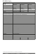
PSI 5000 A Serie 1.8.3 Spezifische technische Daten Modell 160 W PSI 5040-10 A PSI 5080-05 A PSI 5200-02 A Netzspannung 90...264 V AC 90...264 V AC 90...264 V AC Netzanschluß 1ph,N,PE 1ph,N,PE 1ph,N,PE Netzfrequenz 50/60 Hz 50/60 Hz 50/60 Hz Netzsicherung (intern) MT 4 A MT 4 A MT 4 A Ableitstrom < 3.5 mA < 3.5 mA < 3.5 mA Leistungsfaktor ~ 0.99 ~ 0.99 ~ 0.
PSI 5000 A Serie Modell 160 W PSI 5040-10 A PSI 5080-05 A PSI 5200-02 A Steuereingänge U, I, P U, I, P U, I, P Monitorausgänge Meldesignale U, I DC ein/aus, Fernst. ein/aus CV, OVP, OT U, I DC ein/aus, Fernst. ein/aus CV, OVP, OT U, I DC ein/aus, Fernst. ein/aus CV, OVP, OT Galvanische Trennung zum Gerät Max. 1500 V DC Max. 1500 V DC Max.
PSI 5000 A Serie Modell 320 W PSI 5040-20 A PSI 5080-10 A PSI 5200-04 A Netzspannung 90...264 V AC 90...264 V AC 90...264 V AC Netzanschluß 1ph,N,PE 1ph,N,PE 1ph,N,PE Netzfrequenz 50/60 Hz 50/60 Hz 50/60 Hz Netzsicherung (intern) MT 4 A MT 4 A MT 4 A Ableitstrom < 3.5 mA < 3.5 mA < 3.5 mA Leistungsfaktor ~ 0.99 ~ 0.99 ~ 0.
PSI 5000 A Serie Modell 320 W PSI 5040-20 A PSI 5080-10 A PSI 5200-04 A Steuereingänge U, I, P U, I, P U, I, P Monitorausgänge Meldesignale U, I DC ein/aus, Fernst. ein/aus CV, OVP, OT U, I DC ein/aus, Fernst. ein/aus CV, OVP, OT U, I DC ein/aus, Fernst. ein/aus CV, OVP, OT Galvanische Trennung zum Gerät Max. 1500 V DC Max. 1500 V DC Max.
PSI 5000 A Serie Modell 640 W PSI 5040-40 A PSI 5080-20 A PSI 5200-10 A Netzspannung 90...264 V AC 90...264 V AC 90...264 V AC - mit zusätzlichem Derating 90...150 V AC 90...150 V AC 90...
PSI 5000 A Serie Modell 640 W PSI 5040-40 A PSI 5080-20 A PSI 5200-10 A Steuereingänge U, I, P U, I, P U, I, P Monitorausgänge Meldesignale U, I DC ein/aus, Fernst. ein/aus CV, OVP, OT U, I DC ein/aus, Fernst. ein/aus CV, OVP, OT U, I DC ein/aus, Fernst. ein/aus CV, OVP, OT Galvanische Trennung zum Gerät Max. 1500 V DC Max. 1500 V DC Max.
PSI 5000 A Serie 1.8.4 Ansichten Bild 1 - Vorderseite Bild 2 - Rückseite A - Netzschalter B - Bedienteil C - DC-Ausgang D - Schraubklemme mit Hilfsausgang und Fernfühlung E - Steuerungsschnittstellen F - Lüftungsaustritt G - Netzanschluß mit Netzsicherung EA Elektro-Automatik GmbH Helmholtzstr. 31-33 • 41747 Viersen Telefon: 02162 / 3785-0 Telefax: 02162 / 16230 www.elektroautomatik.de ea1974@elektroautomatik.
Bild 3 - Seiteansicht von rechts, mit Lüftungsschlitzen, 640 W-Ausführung Bild 4 - Seitenansicht von rechts, mit Lüftungsschlitzen, 160 W / 320 W-Ausführung PSI 5000 A Serie Seite 16 EA Elektro-Automatik GmbH Helmholtzstr. 31-33 • 41747 Viersen Telefon: 02162 / 3785-0 Telefax: 02162 / 16230 www.elektroautomatik.de ea1974@elektroautomatik.
PSI 5000 A Serie Bild 5 - Bedienfeld Übersicht der Bedienelemente am Bedienfeld Für eine genaue Erläuterung siehe Abschnitt „1.9.4. Die Bedieneinheit (HMI)“. (1) Anzeige Dient zur Anzeige von Sollwerten, Istwerten und Status. Tastenfeld (5 Tasten) Taste Recall: Abrufen der gespeicherten Sollwertsätze (siehe 3.4.6) Taste OVP/OCP: Umschaltung auf Anzeige und Einstellmodus für OVP-, OCP- und OPP-Werte (2) Taste Local: Aktivierung / Deaktivierung der Fernsteuerungssperre bzw.
PSI 5000 A Serie 1.9 Aufbau und Funktion 1.9.1 Allgemeine Beschreibung Die elektronischen DC-Labornetzgeräte der Serie PSI 5000 A sind durch ihre recht kompakten Tischgehäuse besonders für den Einsatz in Laboren, Werkstätten, Schulen und andere Ausbildungseinrichtungen geeignet, wo variable Spannungen und kleine Leistungen gebraucht werden.
PSI 5000 A Serie • Bereich Sollwerte (mittlerer Teil) Die Sollwerte Spannung und Strom oder Leistung sind bei manueller Bedienung mit den unter der Anzeige befindlichen Drehknöpfen verstellbar, wobei durch Druck auf den jeweiligen Drehknopf zwischen Fein- und Grobeinstellung (Fine) umgeschaltet werden kann. Der linke Drehknopf ist dabei, je nach momentanem Einstellmodus, entweder der Spannung bzw. dem Wert wie OVP oder der Leistung bzw. dem Wert OPP zugeordnet. Der rechte Drehknopf ist immer dem Strom bzw.
PSI 5000 A Serie 1.9.5 USB-Port Der USB-Port Typ B auf der Rückseite des Gerätes dient zur Kommunikation mit dem Gerät, sowie zur Firmwareaktualisierung. Über das mitgelieferte USB-Kabel kann das Gerät mit einem PC verbunden werden (USB 2.0, USB 3.0). Der Treiber wird auf CD mitgeliefert bzw. ist als Download verfügbar und installiert einen virtuellen COM-Port. Details zur Fernsteuerung sind in weiterer Dokumentation auf der Webseite des Geräteherstellers bzw. auf der mitgelieferten CD zu finden.
PSI 5000 A Serie 2. Installation & Inbetriebnahme 2.1 Lagerung 2.1.1 Verpackung Es wird empfohlen, die komplette Transportverpackung (Lieferverpackung) für die Lebensdauer des Gerätes aufzubewahren, um sie für den späteren Transport des Gerätes an einen anderen Standort oder Einsendung des Gerätes an den Hersteller zwecks Reparatur wiederverwenden zu können. Im anderen Fall ist die Verpackung umweltgerecht zu entsorgen. 2.1.
PSI 5000 A Serie 2.3.3 Anschließen an das Stromnetz (AC) • Das Anschließen des Gerätes mittels des mitgelieferten Netzkabels kann an jeder Wandsteckdose bzw. Steckdosenverteilung erfolgen, die über einen Schutzkontakt verfügt • Bei Verwendung einer Steckdosenverteilung muß die Gesamtleistung aller angeschlossenen Geräte beachtet werden, so daß der Maximalstrom (Leistung ÷ Minimalspannung) nicht den für die Steckdosenverteilung und der Hauptanschlußsteckdose definierten max.
PSI 5000 A Serie 2.3.5 Erdung des DC-Ausgangs Grundsätzlich können einzeln betriebene Geräte entweder am DC-Minuspol oder DC-Pluspol geerdet, sprich direkt mit PE verbunden werden. Bei Reihenschaltung hingegen gibt es zusätzliche Einschränkungen, weil bei Erdung des Pluspols ein oder mehrere DC-Minuspole im Potential negativ verschoben werden. Hierbei darf kein DC-Minuspol mehr als 200 V Differenz zu PE haben. Im Fall, daß es erforderlich ist, den DC-Plusausgang zu erden ergibt sich z. B.
PSI 5000 A Serie Bild 7 - Beispiel Fernfühlungsverdrahtung bei Nutzung des Hauptausgangs 2.3.7 Anschließen der analogen Schnittstelle Der 15polige Anschluß (Typ: Sub-D, D-Sub) auf der Rückseite ist eine analoge Schnittstelle. Um diesen mit einer steuernden Hardware (PC, elektronische Schaltung) zu verbinden, ist ein handelsüblicher Sub-D-Stecker erforderlich (nicht im Lieferumfang enthalten).
PSI 5000 A Serie 2.3.9 Erstinbetriebnahme Bei der allerersten Inbetriebnahme nach dem Erwerb des Gerätes und der Erstinstallation sind zusätzliche Maßnahmen zu ergreifen: • Überprüfen Sie die von Ihnen verwendeten Anschlußkabel für DC auf ausreichenden Querschnitt! • Überprüfen Sie die werkseitigen Einstellungen bezüglich Sollwerte, Sicherheits- und Überwachungsfunktionen daraufhin, daß Sie für Ihre Anwendung passen und stellen Sie sie ggf.
PSI 5000 A Serie 3. Bedienung und Verwendung 3.1 Personenschutz • Um Sicherheit bei der Benutzung des Gerätes zu gewährleisten, darf das Gerät nur von Personen bedient werden, die über die erforderlichen Sicherheitsmaßnahmen im Umgang mit gefährlichen elektrischen Spannungen unterrichtet worden sind • Schalten Sie das Gerät bei Umkonfiguration der Last und des DC-Anschlusses immer mit dem Netzschalter aus und nicht nur mit der Funktion „Ausgang aus“! 3.
PSI 5000 A Serie 3.3 Alarmzustände Dieser Abschnitt gibt nur eine Übersicht über mögliche Alarmzustände. Was zu tun ist im Fall, daß Ihr Gerät einen Alarm anzeigt, wird in Abschnitt „3.6. Alarme und Überwachung“ erläutert. Grundsätzlich werden alle Alarmzustände optisch (Meldung in der Anzeige) und als auslesbarer Status über digitale Schnittstelle signalisiert. Außerdem wird bei den meisten Alarmen der DC-Ausgang des Gerätes ausgeschaltet. 3.3.
PSI 5000 A Serie 3.4 Manuelle Bedienung 3.4.1 Einschalten des Gerätes Das Gerät sollte möglichst immer am Netzschalter (Vorderseite) eingeschaltet werden. Alternativ kann es über eine externe Trennvorrichtung (Schütz) mit entsprechender Strombelastbarkeit netzseitig geschaltet werden. Nach dem Einschalten und einer gewissen Hochlaufzeit wird der Zustand des DC-Ausgangs wiederhergestellt, so wie er beim letzten Ausschalten war, also entweder ein oder aus.
PSI 5000 A Serie 3.4.4 Schutzfunktionen manuell konfigurieren Neben einstellbaren Sollwerten bietet das Gerät die Möglichkeit, die Ausgangsgrößen Strom, Spannung und Leistung auf bestimmte, einstellbare Schwellen hin zu überwachen und bei Erreichen den DC-Ausgang abzuschalten, sowie einen Alarm zu melden. Diese Schutzfunktionen nennen sich kurz OVP (overvoltage protection, Überspannungsschutz), OCP (overcurrent protection, Überstromschutz) und OPP (overpower protection, Überleistungsschutz).
PSI 5000 A Serie 3.4.6 Recall-Funktion Die Recall-Funktion (deutsch: abrufen) dient zur Speicherung und zum schnellen Abrufen häufig benutzter Sollwerte (U, I) und Werte der Schutzfunktionen (OVP, OCP), mit Ausnahme der Leistung und des Wertes OPP. Man kann somit schnell zwischen verschiedenen Sollwertsätzen wechseln ohne die Sollwerte ständig neu einstellen zu müssen. Es stehen 9 Speicherplätze für Sollwertsätze zur Verfügung.
PSI 5000 A Serie 3.5 Fernsteuerung 3.5.1 Allgemeines Fernsteuerung ist grundsätzlich über die eingebaute analoge oder eine der eingebauten digitalen Schnittstellen (USB, Ethernet/LAN) möglich. Wichtig ist dabei, daß entweder nur die analoge oder eine digitale im Eingriff sein kann.
PSI 5000 A Serie Die Netzwerkparameter können bei Geräten dieser Serie nur von außen geändert werden. Das kann über Befehle (SCPI, ModBus) geschehen, die vorzugsweise über den USB-Port geschickt werden, oder über die Webseite. In beiden Fällen ist Fernsteuerungsmodus erforderlich, der zunächst vom Anwender aktiviert werden muß (Befehl: SYST:LOCK ON). Dieser kann jedoch durch den Zustand LOCAL (vorn am Gerät mit Taste setzbar, im Display angezeigt) verhindert sein.
PSI 5000 A Serie 3.5.4 Fernsteuerung über Analogschnittstelle (AS) 3.5.4.
PSI 5000 A Serie 3.5.4.3 Spezifikation der Analogschnittstelle Pin Name Typ* Bezeichnung 1 VSEL AI Sollwert Spannung 2 CSEL AI Sollwert Strom 3 VREF AO Referenzspannung 4 DGND POT Bezugspotential für alle digitalen Signale Pegel 0…10 V bzw. 0...5 V entsprechen 0..100% von UNenn 0…10 V bzw. 0...5 V entsprechen 0..100% von INenn Elektrische Eigenschaften Genauigkeit < 0,2% **** Eingangsimpedanz Ri >40 k...
PSI 5000 A Serie 3.5.4.5 Prinzipschaltbilder der Pins Digitaler Eingang (DI) Die innere Beschaltung gibt vor, daß ein möglichst niederohmiger Schalter zu verwenden ist (Relaiskontakt, Schalter, Schütz o.ä.), um das Signal sauber nach DGND zu schalten. + +10V 12V 4.7k 3.5.4.6 Analoger Eingang (AI) V~0.5 AGND Ein digitaler Ausgang einer Schaltung oder SPS könnte nicht ausreichend sein, wenn nicht vom Typ „open collector“.
PSI 5000 A Serie Ist der DC-Ausgang bereits eingeschaltet, bewirkt der Pin die Abschaltung dessen bzw. später erneutes Einschalten, ähnlich wie bei aktivierter Fernsteuerung: DCPin Ausgang „REM-SB“ ist ein HIGH LOW HIGH LOW + + + + + Parameter Verhalten „REM-SB“ Der DC-Ausgang bleibt eingeschaltet.
PSI 5000 A Serie 3.6 Alarme und Überwachung 3.6.1 Begriffsdefinition Grundsätzlich ist bei Gerätealarmen (siehe auch „3.3. Alarmzustände“) nur von gemeldeten Zuständen wie Überspannung oder Übertemperatur die Rede, die im Zusammenhang mit teils einstellbaren Überwachungsgrenzen auftreten können. Diese Alarme werden immer mindestens als ablesbare Meldung in der Anzeige herausgegeben, sowie zusätzlich als abfragbarer Status bei der digitalen Fernsteuerung / Überwachung. 3.6.
PSI 5000 A Serie 3.7 Weitere Anwendungen 3.7.1 Parallelschaltung Mehrere Geräte gleicher Art und möglichst gleichen Modells können zu einer Parallelschaltung verbunden werden, um eine höhere Gesamtleistung zu erzielen. Es gibt keine zusätzliche Unterstützung durch die Firmware oder Hardware in Bezug auf Ausregelung und Stromsymmetrierung, so daß jedes Gerät in der Parallelschaltung bezüglich seiner Sollwerte und Einstellungen separat eingestellt bzw. ferngesteuert gesetzt werden muß.
PSI 5000 A Serie 4. Instandhaltung & Wartung 4.1 Wartung / Reinigung Die Gerät erfordern keine Wartung. Reinigung kann, jenachdem in welcher Umgebung sie betrieben werden, früher oder später für den internen Lüfter nötig sein. Dieser dient zur Kühlung der internen Komponenten, die durch die zwangsweise entstehende, jedoch geringe Verlustleistung erhitzt werden. Stark verdreckte Lüfter können zu unzureichender Luftzufuhr führen und damit zu vorzeitiger Abschaltung des DC-Ausgangs wegen Überhitzung bzw.
PSI 5000 A Serie 5. Zubehör und Optionen 5.1 Übersicht 6. Service & Support 6.1 Übersicht 6.2 Kontaktmöglichkeiten Zubehör und Optionen werden, sofern nötig, mit eigener Dokumentation geliefert und werden in diesem Dokument nicht näher erläutert. Reparaturen, falls nicht anders zwischen Anwender und Lieferant ausgemacht, werden durch den Hersteller durchgeführt. Dazu muß das Gerät im Allgemeinen an den Hersteller eingeschickt werden. Es wird keine RMA-Nummer benötigt.
EA-Elektro-Automatik GmbH & Co. KG Entwicklung - Produktion - Vertrieb Helmholtzstraße 31-33 41747 Viersen Telefon: 02162 / 37 85-0 Telefax: 02162 / 16 230 ea1974@elektroautomatik.de www.elektroautomatik.
Elektro-Automatik Operating Guide PSI 5000 A DC Laboratory Power Supply Doc ID: PSI5EN Revision: 06 Date: 04/2015
PSI 5000 A Series TABLE OF CONTENTS 1 GENERAL 1.1 1.1.1 1.1.2 1.1.3 1.1.4 1.2 1.3 1.4 1.5 1.6 1.7 1.7.1 1.7.2 1.7.3 1.7.4 1.7.5 1.8 1.8.1 1.8.2 1.8.3 1.8.4 1.9 1.9.1 1.9.2 1.9.3 1.9.4 1.9.5 1.9.6 1.9.7 1.9.8 2 About this document.......................................4 Retention and use...........................................4 Copyright.........................................................4 Validity.............................................................4 Symbols and warnings................
PSI 5000 A Series 1. General 1.1 About this document 1.1.1 Retention and use This document is to be kept in the vicinity of the equipment for future reference and explanation of the operation of the device. This document is to be delivered and kept with the equipment in case of change of location and/or user. 1.1.2 Copyright Reprinting, copying, also partially, usage for other purposes as foreseen of this manual are forbidden and breach may lead to legal process. 1.1.
PSI 5000 A Series 1.4 Disposal of equipment 1.5 Product key A piece of equipment which is intended for disposal must, according to European laws and regulations (ElektroG, WEEE) be returned to the manufacturer for scrapping, unless the person operating the piece of equipment or another, delegated person is conducting the disposal.
PSI 5000 A Series 1.7 Safety 1.7.1 Safety notices Mortal danger - Hazardous voltage • Electrical equipment operation means that some parts can be under dangerous voltage. Therefore all parts under voltage must be covered! This basically applies to all models, though 40 V models according to SELV can not generate hazardous DC voltage. • All work on connections must be carried out under zero voltage (output not connected to load) and may only be performed by qualified and informed persons.
PSI 5000 A Series 1.7.3 Responsibility of the operator Operator is any natural or legal person who uses the equipment or delegates the usage to a third party, and is responsible during its usage for the safety of the user, other personnel or third parties. The equipment is intended for industrial operation. Therefore the operators are governed by the legal safety regulations.
PSI 5000 A Series 1.7.5 Alarm signals The equipment offers various possibilities for signalling alarm conditions, however, not for danger situations. The signals may be optical (on the display as text) or electronic (pin/status output of an analog interface). All alarms will cause the device to switch off the DC output permanently or temporarily.
PSI 5000 A Series 1.8.3 Specific technical data Model 160 W PSI 5040-10 A PSI 5080-05 A PSI 5200-02 A Input voltage 90...264 V AC 90...264 V AC 90...264 V AC Input connection 1ph,N,PE 1ph,N,PE 1ph,N,PE Input frequency 50/60 Hz 50/60 Hz 50/60 Hz Input fuse (internal) MT 4 A MT 4 A MT 4 A Leak current < 3.5 mA < 3.5 mA < 3.5 mA Power factor ~ 0.99 ~ 0.99 ~ 0.99 Max. output voltage UMax 40 V 80 V 200 V Max. output current IMax 10 A 5A 2A Max.
PSI 5000 A Series Model 160 W PSI 5040-10 A PSI 5080-05 A PSI 5200-02 A Set value inputs U, I, P U, I, P U, I, P Actual value output Status signals U, I DC on/off, Remote on/off CV, OVP, OT U, I DC on/off, Remote on/off CV, OVP, OT U, I DC on/off, Remote on/off CV, OVP, OT Galvanic isolation to the device Max. 1500 V DC Max. 1500 V DC Max.
PSI 5000 A Series Model 320 W PSI 5040-20 A PSI 5080-10 A PSI 5200-04 A Input voltage 90...264 V AC 90...264 V AC 90...264 V AC Input connection 1ph,N,PE 1ph,N,PE 1ph,N,PE Input frequency 50/60 Hz 50/60 Hz 50/60 Hz Input fuse (internal) MT 4 A MT 4 A MT 4 A Leak current < 3.5 mA < 3.5 mA < 3.5 mA Power factor ~ 0.99 ~ 0.99 ~ 0.99 Max. output voltage UMax 40 V 80 V 200 V Max. output current IMax 20 A 10 A 4A Max.
PSI 5000 A Series Model 320 W PSI 5040-20 A PSI 5080-10 A PSI 5200-04 A Set value inputs U, I, P U, I, P U, I, P Actual value output Status signals U, I DC on/off, Remote on/off CV, OVP, OT U, I DC on/off, Remote on/off CV, OVP, OT U, I DC on/off, Remote on/off CV, OVP, OT Galvanic isolation to the device Max. 1500 V DC Max. 1500 V DC Max.
PSI 5000 A Series Model 640 W PSI 5040-40 A PSI 5080-20 A PSI 5200-10 A Input voltage 90...264 V AC 90...264 V AC 90...264 V AC - with additional derating 90...150 V AC 90...150 V AC 90...150 V AC Input connection 1ph,N,PE 1ph,N,PE 1ph,N,PE Input frequency 50/60 Hz 50/60 Hz 50/60 Hz Input fuse (internal) MT 8 A MT 8 A MT 8 A Leak current < 3.5 mA < 3.5 mA < 3.5 mA Power factor ~ 0.99 ~ 0.99 ~ 0.99 Max. output voltage UMax 40 V 80 V 200 V Max.
PSI 5000 A Series Model 640 W PSI 5040-40 A PSI 5080-20 A PSI 5200-10 A Set value inputs U, I, P U, I, P U, I, P Actual value output Status signals U, I DC on/off, Remote on/off CV, OVP, OT U, I DC on/off, Remote on/off CV, OVP, OT U, I DC on/off, Remote on/off CV, OVP, OT Galvanic isolation to the device Max. 1500 V DC Max. 1500 V DC Max.
PSI 5000 A Series 1.8.4 Views Figure 1 - Front side Figure 2 - Back side A - Mains switch B - Control panel C - DC output D - Screw terminal with auxiliary DC output and sense input E - Control interfaces F - Exhaust G - AC input socket with fuse EA Elektro-Automatik GmbH Helmholtzstr. 31-33 • 41747 Viersen Germany Fon: +49 2162 / 3785-0 Fax: +49 2162 / 16230 www.elektroautomatik.de ea1974@elektroautomatik.
Figure 3 - View from right side, with ventilation slots, 640 W model Figure 4 - View from right side, with ventilation slots, 160 W / 320 W model PSI 5000 A Series Page 16 EA Elektro-Automatik GmbH Helmholtzstr. 31-33 • 41747 Viersen Germany Fon: +49 2162 / 3785-0 Fax: +49 2162 / 16230 www.elektroautomatik.de ea1974@elektroautomatik.
PSI 5000 A Series Figure 5 - Control Panel Overview of the elements of the operating panel For a detailed description see section „1.9.4. The control panel (HMI)“. (1) Display Used for indication of set values, actual values and status. Button bank (5 buttons) Button Recall: Recalls stored presets (see 3.4.6) Button OVP/OCP: Switches to adjustment of OVP, OCP and OPP values (2) Button Local: Activation / deactivation of the remote control inhibit or abort of remote control (see 3.5.
PSI 5000 A Series 1.9 Construction and function 1.9.1 General description The electronic DC laboratory power supplies of the PSI 5000 A series are especially suitable for laboratories, workshops, school and other educational facilities due to their compact construction in a desktop enclosure. For remote control using a PC or PLC the devices are provided as standard with a 3-way interface on the rear side. It includes a USB port, an Ethernet port and an analog connector.
PSI 5000 A Series The left hand rotary knob is assigned either to the output voltage and related parameter OVP or the power and the related parameter OPP, whereas the right hand rotary knobs is always assigned to the output current and related parameter OCP. In remote control condition, the set values given from remote are displayed here. This row furthermore indicates alarm conditions. See „3.6. Alarms and supervision“ for details.
PSI 5000 A Series 1.9.5 USB port The USB port on the back side of the device is provided for communication with the device and for firmware updates. The included USB cable can be used to connect the device to a PC (USB 2.0, USB 3.0). The driver is delivered on the included CD or is available as download and installs a virtual COM port. Details for remote control can be found in external documentation, a general programming guide, on the web site of the manufacturer or on the included CD.
PSI 5000 A Series 2. Installation & commissioning 2.1 Storage 2.1.1 Packaging It is recommended to keep the complete transport packaging for the lifetime of the device for relocation or return to the manufacturer for repair. Otherwise the packaging should be disposed of in an environmentally friendly way. 2.1.2 Storage In case of long term storage of the equipment it is recommended to use the original packaging or similar.
PSI 5000 A Series 2.3.
PSI 5000 A Series 2.3.5 Grounding of the DC output Individually operated devices can always be grounded from the DC minus or DC plus pole, i.e. one of both can be directly connected to PE. However, when using series connection restrictions apply, because when grounding the DC plus pole of the series connection, the DC minus poles of all units are shifted in negative direction against PE and this is only allowed up to 200 V DC for any DC minus.
PSI 5000 A Series Figure 7 - Example for remote sensing wiring when using the main output 2.3.7 Connecting the analog interface The 15 pole connector (Type: Sub-D, D-Sub) on the rear side is an analog interface. To connect this to a controlling hardware (PC, electronic circuit), a standard plug is necessary (not included in the scope of delivery). It is generally advisable to switch the device completely off before connecting or disconnecting this connector, but at least the DC output.
PSI 5000 A Series 2.3.
PSI 5000 A Series 3. Operation and application 3.1 Personal safety • In order to guarantee safety when using the device, it is essential that only persons operate the device who are fully acquainted and trained in the required safety measures to be taken when working with dangerous electrical voltages • Whenever the load and DC output connection are being re-configured, the device should be disconnected from the mains, not only the DC output switched off! 3.
PSI 5000 A Series 3.3 Alarm conditions This section only gives an overview about device alarms. What to do in case your device indicates an alarm condition is described in section „3.6. Alarms and supervision“. As a basic principle, all alarm conditions are signalled optically (in the display) and as a readable status via the digital interface. With most alarms occurring, the DC output of the device is switched off. 3.3.
PSI 5000 A Series 3.4 Manual operation 3.4.1 Switching the device on The device should, as far as possible, always be switched on using the toggle switch on the front of the device. Alternatively this can take place using an external cutout (contactor, circuit breaker) of suitable current capacity. After switching on and a certain start-up time, the device will be ready for use.
PSI 5000 A Series 3.4.4 Manually configure protections Along with adjustable set values, the device offers excess protections related to voltage, current and power, which are intended to protect the possibly expensive load hardware. They are configurable in form of adjustable thresholds that the device supervises and in case of excess it will switch off the DC output. Those protections are OVP (overvoltage protection), OCP (overcurrent protection) and OPP (overpower protection).
PSI 5000 A Series 3.4.6 Recall feature The recall feature is intended to easily recall presets of often used set values (U, I) and protection thresholds (OVP, OCP), except the power set value and OPP threshold. With this, the user can switch between the presets without having to adjust every time again. There are 9 presets for custom definition. Saving and recalling the presets can only be done while the DC output is switched off. ►►How to adjust and save a preset 1.
PSI 5000 A Series 3.5 Remote control 3.5.1 General Remote control is principally possible via any of the built-in interface ports (USB, Ethernet/LAN, analog). Important here is that only the analog or one digital interface can be in control. It means that if, for example, an attempt were to be made to switch to remote control via the digital interface whilst analog remote control is active (pin Remote = LOW) the device would report an error at the digital interface.
PSI 5000 A Series The network parameters can only be modified from external. This can be done using commands (SCPI, ModBus), which are preferably sent via USB, or the website. In both cases and in order to modify settings, it requires the user to activate remote control first (command: SYST:LOCK ON), which might be inhibited by status LOCAL being active (see front panel, pushbutton LOCAL, display status LOCAL).
PSI 5000 A Series 3.5.4 Remote control via the analog interface (AI) 3.5.4.
PSI 5000 A Series 3.5.4.3 Analog interface specification Pin Name Type* Description 1 VSEL AI Set voltage value 2 CSEL AI Set current value 3 VREF AO Reference voltage 4 DGND POT Ground for all digital signals Levels 0…10 V or. 0...5 V correspond to 0..100% of UNom 0…10 V or. 0...5 V correspond to 0..
PSI 5000 A Series 3.5.4.5 Simplified diagram of the pins Digital Input (DI) + The internal circuit requires that a switch with low resistance should be used (relay, switch, circuit breaker etc.) in order to send a clean signal to the DGND. 3.5.4.6 V~0.5 12V A quasi open collector, realised as high resistance pull-up against the internal supply. In condition LOW it can carry no load, merely switch, as shown in the diagram with a relay as example. High resistance input (impedance >40 k....
PSI 5000 A Series In case the DC output is already switched on, toggling the pin will switch the DC output off, similar to what it does in analog remote control: DCoutput is on Pin „REM-SB“ HIGH LOW HIGH LOW + + + + + Parameter Behaviour „REM-SB“ DC output remains on, nothing is locked. It can be switched on normal or off by pushbutton or digital command. inverted inverted normal DC output will be switched off and locked. Later it can be switched on again by toggling the pin.
PSI 5000 A Series 3.6 Alarms and supervision 3.6.1 Definition of terms Device alarms (see „3.3. Alarm conditions“) are defined as conditions like overvoltage or overtemperature, which can occur in relation to protection feature with partly adjustable thresholds. The alarms are always indicated in the front display and are as well available as readable status via digital interface when controlling or just monitoring remotely. 3.6.
PSI 5000 A Series 3.7 Other applications 3.7.1 Parallel operation Multiple devices of same kind and model can be connected in parallel in order to create a system with higher total current and hence higher power. There is no additional support from hardware or software for this kind of operation, regarding voltage regulation and current balancing. Every unit would have to be adjusted like a standalone device, either manually or remotely.
PSI 5000 A Series 4. Service and maintenance 4.1 Maintenance / cleaning The device needs no maintenance. Cleaning may be needed for the internal fans, the frequency of cleanse is depending on the ambient conditions. The fans serve to cool the components which are heated by the inherent power loss. Heavily dirt filled fans can lead to insufficient airflow and therefore the DC output would switch off too early due to overheating or possibly lead to defects.
EA-Elektro-Automatik GmbH & Co. KG Entwicklung - Produktion - Vertrieb Helmholtzstraße 31-33 41747 Viersen Telefon: 02162 / 37 85-0 Telefax: 02162 / 16 230 ea1974@elektroautomatik.de www.elektroautomatik.