
User manual


Page 22
PSI 5000 A Series
www.elektroautomatik.de
ea1974@elektroautomatik.de
EA Elektro-Automatik GmbH
Helmholtzstr. 31-33 • 41747 Viersen
Germany
Fon: +49 2162 / 3785-0
Fax: +49 2162 / 16230
2.3.3 Connection to AC supply
• The device can be connected to any wall socket or power strip, as long as those feature a
ground conductor (PE)
• When connecting the device to a power strip, along with other electric devices, it is important
to consider the total power consumption of all devices on the strip, so that the maximum cur-
rent(power÷minimumvoltage)doesnotexceedthedenitionforthewallsocket,thepower
strip and/or main distribution
The device is delivered with a 3 pole power cord.
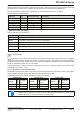
Nominal power Default connection rating Connection type
160 W 230 V, 50 Hz, ~2 A Wall socket
320 W 230 V, 50 Hz, ~4 A Wall socket
640 W 230 V, 50 Hz, ~8 A Wall socket
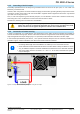
2.3.4 Connection to DC loads
The device features two DC output connectors. The main output is on the front side and the auxiliary output on the
rearside.Whilethemainoutputisdenedfortheratedoutputcurrent,theauxoutputcanonlybeusedupto32A.
For the connection of loads or parallel connection of multiple units, following applies:
• With the 40 A model, it is not allowed to connect a load to the auxiliary output which
could permanently draw more than 32 A, unless the current is limited to 32 A by cur-
rent set value
• It is not allowed to connect multiple units in parallel on their auxiliary outputs and
then connecting the load on one of the main outputs on the front, unless the total
current does not exceed 32 A
• With the 40 A model, it is not allowed to use and plug 4mm Büschel plugs on the main
DC output when working with loads that can draw more 35 A, unless the output cur-
rent is limited to 35 A by current set value
Both DC outputs are not protected by a fuse. The cross section of the connection cable is determined by the cur-
rent consumption, cable length and ambient temperature.
For cables up to 1.5 m and average ambient temperature up to 50°C, we recommend:
up to 10 A: 0,75 mm² (AWG18)
up to 20 A: 2.5 mm² (AWG12)
up to 40 A: 6 mm² (AWG8)
per lead (multi-conductor, insulated, openly suspended). Single cables of, for example, 6 mm² may be replaced
by e.g. 2x 2.5 mm² etc. If the cables are long then the cross section must be increased to avoid voltage loss and
overheating.
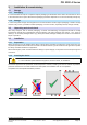
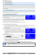
2.3.4.1 Possible methods of connections on the main DC output
The main output on the front is of type screw & plug and can be used with:
• 4 mm system plugs (Büschel) for max. 35 A
• Spade lugs (4 mm or bigger)
• Soldered cable ends
• Cable end sleeves (using the cross hole, 1.5 mm, max. 10 A)
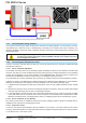
2.3.4.2 Possible methods of connections on the auxiliary DC output
The auxiliary output on the rear is limited for max. 32 A, is of type screw terminal and can be used with:
• Soldered cable ends
• Cable end sleeves (various sizes)
• Spade lugs (4 mm)