
User manual

Page 63
EA Elektro-Automatik GmbH
Helmholtzstr. 31-33 • 41747 Viersen
Germany
Fon: +49 2162 / 3785-0
Fax: +49 2162 / 16230
www.elektroautomatik.de
ea1974@elektroautomatik.de
PSI 9000 DT Series
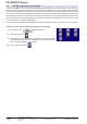
3.9 The function generator
3.9.1 Introduction
The built-in function generator (short: FG) is able to create various signal forms and apply them to the set value
of voltage or current.
All functions are based on a customisable arbitrary generator. In manual operation, the separate functions are
availableforselectionandcongurationonthefrontpanel.Inremotecontrol,allfunctionsareconguredusing
so-called sequences with 8 parameters each.
Thefollowingfunctionsareretrievable,congurableandcontrollable:
Function Usable
on
Short description
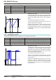
Sine wave U, I Sine wave generation with adjustable amplitude, offset and frequency
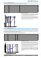
Triangle U, I Triangular wave signal generation with adjustable amplitude, offset, gain and decay times
Rectangular U, I Rectangular wave signal generation with adjustable amplitude, offset and duty cycle
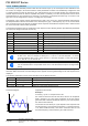
Trapezoid U, I Trapezoidal wave signal generation with adjustable amplitude, offset, rise time, pulse
time, fall time, idle time
DIN 40839 - Simulated automobile engine start curve according to DIN 40839 / EN ISO 7637, split
into5curvesequences,eachwithastartvoltage,nalvoltageandtime
Arbitrary U, I Generationofaprocesswithupto100freelycongurablesteps,eachwithastartand
end value (AC/DC), start and end frequency, phase angle and total duration
Ramp U, I Generation of a linear rise or fall ramp with start and end values and time before and
after the ramp
Whilst R mode is activated, access to the function generator is not available.
3.9.2 General
3.9.2.1 Restrictions
The function generator is not accessible, neither for manual acces, nor for remote control, if
• resistance mode (R/I adjustment mode, also called UIR mode) is active.
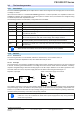
3.9.2.2 Principle
The power supply unit cannot be considered as high power function generator, because it is only post-connected
to the FG. Thus the typical characteristics of a voltage and current source remain. Rise and fall times, caused by
capacitor charge/discharge, affect the resulting signal on the DC output. While the FG is able to generate a sine
wave with 1000 Hz or more, the power supply will never be able to follow the generated signal 1:1.
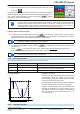
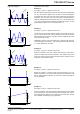
Depiction of principle: Affect of the power supply on functions:
FG PSI
DC out
+
--
C
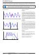
The resulting wave form on the DC output heavily depends on the frequency of the selected wave, its amplitude
and power supply model. The effects of the power supply on the wave can only be partially compensated. For
instance, it is possible to decrease the output voltage sinking time at low load conditions by adding a base load,
one that is either permanently connected or temporarily switched.
The minimum values of all adjustable parameters of the function generator, like for example
a time of 0.1 ms, are not dened to match what a power supply device resp. every particular
model can truly achieve.