
User manual


14
© 2006, Elektro-Automatik GmbH & Co. KG
Irrtümer und Änderungen vorbehalten
EN
© 2009, Elektro-Automatik GmbH & Co. KG
General
Introduction
The microcontroller controlled battery chargers of the
BC 800 R series are designed for wall mount and work
with an airow based cooling.
They are intended to charge different type of lead
batteries. The three-stage, temperature compensating
charging procedure allows fast, complete and careful
charging of the batteries.
Furthermore, the devices feature a power supply mode
where the output voltage becomes adjustable.
The power output is protected against false polarity
connection, is short-circuit-proof and overload-proof.
For protection of the loads, the devices also feature an
overvoltage protection (OVP). At an overtemperature
(OT) event, the power output will be switched off until
the unit has cooled down and automatically switch on
again.
Visual check
After receipt, the unit has to be checked for signs of phy-
sical damage. If any damage is found, the unit may not
be operated. Also contact your dealer immediately.
Scope of delivery
1 x Battery charger unit
1 x Printed user manual
1 x Temperature sensor LM335Z (10mV/K)
1 x Mounting kit
2 x Pieces of shrinking hose
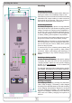
Installation
Mounting
The device is designed for wall mount. It is required
to mount it in a way that allows unimpeded air ow
through the ventilation slots. Take care for plenty of
space (at least 15cm) below and above the device in
order to ensure proper cooling. The included mounting
kit contains strips that can be attached to the device
in vertical or horizontal position. These strips have drill
holes for screws with up to 5mm thread.
Also see drawing on page 17.
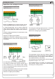
Mains connection
All models are equipped with an active PFC (power
factor correction) and a wide range input. It can be
operated at AC input voltages from 90V to 264V and
mains frequencies of 45Hz up to 65Hz.
The connection is done at the 3pole terminal „Power
Input“ on the front plate. It must only be carried out
by trained technical personnel. Main focus lies on an
appropriate cross section of the mains lead, as well as
the fact that the device does not feature a power switch.
The mains input is fused by a standard 5x20mm fuse,
type T16A, which is located in the fuse holder on the
front plate.
DC output connection
The load is connected to the DC output terminals on
the front using leads with appropriate cross section.
The device can produce dangerous voltages. Thus
the output must be covered when working with the
device. The included shrinking hose can be used, or
something similiar.
Functional description
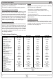
Battery types
The battery chargers can be used to charge different
types of lead batteries, as for example lead-acid, gel
cell or AGM type. Any of the battery types are charged
according to a three-stage, temperature compensating
(only with temperature sensor connected) charging
procedure. The battery type can be selected by a push-
button on the front panel. The related charging proles
mainly differ in the cell voltage (see table below).
Charging procedure
Attention! Defective batteries (U
BatAct
= <0.2 x U
BatNom
)
can not be charged!
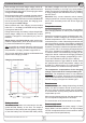
The charging procedure follows an I-U-U characteris-
tics.
The rst phase of the charging stage 1 is a precharge
phase with reduced output current (0.1 x I
Nom
). The
precharge is very effective on deeply discharged batte-
ries with U
BatAct
= >0.2 x U
BatNom
, providing the possibility
to repair and recharge them again. As soon as the
output voltage rises to 0.9 x U
BatNom
or after a maximum
precharge time of 30 minutes, the procedure changes
to normal charge phase.
During normal charge, the battery is charged with full
output current I
Nom
(or with a reduced to 30% output
current I-Limit).
About the device