
User manual


15
© 2009, Elektro-Automatik GmbH & Co. KG
EN
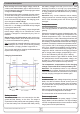
After reaching the normal charge voltage, which de-
pends on the selected battery type, or after a maximum
total of 6 hours charging time, the charging procedure
changes to boost charge.
Boost charge is done with increased charging voltage.
As soon as the charging current becomes <5% of I
Nom
or the boost charge phase time exceeds 1.5 times the
time of the normal charge phase, the charging proce-
dure changes to trickle charge.
When reached and if the charging current remains
below 5% I
Nom
, the battery is indicated as fully charged
by the green status LED.
During trickle charge, the battery is kept charged with
trickle charge voltage for an unlimited time, unless
charging is stopped or interrupted by any error or
blackout.
Boost charge and trickle charge make use the tem-
perature compensation, which is recommend in order
to prevent the batteries from gassing.
Tip: it is possible to manually reduce the output current
by activating the 30% I-Limit. This is done by pressing
the pushbutton „Charging Proles“ longer than 3s.
The I-Limit is useful when charging small batteries that
require lower charging currents.
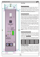
Charging characteristics
Battery terminal
The battery or batteries are connected to the desi-
gnated terminal „Battery“ on the front. The output is
supervised for false polarity and wrong battery voltage.
In case the battery was connected with false polarity,
the battery voltage is too low (<0.2 x U
BatNom
, total
discharge condition) or too high (eg. wrong battery
model), the charging is inhibited to start. The condition
of wrong voltage is also indicated as error by ashing
the LED „Error“.
Attention! Only connect batteries whose battery
voltage matches the nominal charging voltage of the
device. Else the battery and/or the device might get
damaged.
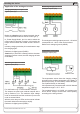
Temperature sensor
It is recommended to use temperature compensation
when charging batteries, in order to prevent dangerous
gassing.
Without the temperature sensor the batteries are char-
ged with a constant voltage that corresponds to an
ambient temperature of 25°C. The sensor is directly
connected to pins 1 and 6 of the analogue interface and
has to be placed in proximity of the battery or attached
to the battery. It is detected and used when the charging
is started. If the device measures temperatures below-
15°C or above +50°C, the charging is stopped and the
LED „Error“ indicates a temperature error by ashing.
In case the sensor is removed during charging or da-
maged, the device continues the charging procedure
with a charge phase voltage corresponding to 25°C.
This is also indicated by the LED „Error“ ashing.
Temperature sensors of type LM335 or similiar, which
are specied with 10mV/K temperature voltage, can
be used. Pin 1 delivers approx. 4.1V and currents from
0.8mA (internal 1k in series to the temp sensor).
The temperature compensation of the charging
voltage is done with 4mV/°C and per battery cell.
Attention! The temperature sensor is only detected
when charging is started. Removing and re-attaching
it will remain considered as if the sensor is not present,
until the charging is stopped and started again.
Remote sense
In order to compensate voltage drops along the load
leads, the device features remote sense inputs on
the front. Here the sensed voltage from the battery
is connected with correct polarity. Remote sense can
compensate up to 2V.
When not using the sense inputs, they just remain open.
It is not required to bridge them to the output.
The cross section of the sense leads is non-critical.
Power supply mode
The device can be used as power supply, if „Power
Supply Mode“ has been selected. The output voltage
can then be adjusted with the trimmer within a limited
range (see technical specications).
Functional description