
User manual


18
© 2006, Elektro-Automatik GmbH & Co. KG
Irrtümer und Änderungen vorbehalten
EN
© 2009, Elektro-Automatik GmbH & Co. KG
The charging procedure is also indicated by the signal
„Charging“ on the analogue interface.
Stopping the charging
The pushbutton „Start / Stop Charging“ is also used to
stop the charging immediately at any phase. The output
will then be switched off and no LED next to the battery
charging level symbols will be lit anymore.
Before connecting or disconnecting the battery the
charging must be stopped!
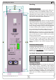
Power Supply Mode
Note: the power supply mode is intended for parallel
standby operation.
The battery charger can be used as a power supply
with limited voltage adjustment range. To select the
power supply mode, use pushbutton „Charging Pro-
les“.
Switching the power output on or off is done by
pressing the button „Start / Stop Charging“.
While the output is on, the green status LED indicates
constant voltage (CV) operation or the red status LED
indicates constant current (CC) operation. Both ope-
ration modes depend on the voltage/current condition
on the output.
The output current is limited to the device‘s nominal
current and can‘t be adjusted.
In order to adjust the output voltage with the trimmer
within the given range, see technical specications, the
output has to be switched on.
Connecting a load should only be done while the output
is switched off. The cross section of the load leads must
match the nominal current of the device.
Charging with reduced current
Batteries with small capacity can be charged with
reduced current by activating the „I-Limit“ feature. It
reduces the charging current of any charging phase
to 30% of the normal level.
The maximum value of the reduced charging current
is stated on the front plate as „I-limit xA“ (next to LED
„Error“). The LED „I-Limit 30%“ indicates the activated
current limitation by being permantly on (as long as no
error is present).
The function can be activated anytime during a
charging.
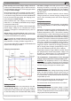
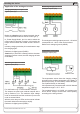
Using the analogue interface
The analogue interface allows to monitor the device‘s
output values (voltage and current) and the condition
(errors) remotely. It can also start or stop a charging.
The monitor outputs represent with 0...10V the nominal
values of the device from 0...100%.
The temperature sensor is also connected to the ana-
logue interface. The clamps are suitable for 20 - 26
AWG wires, dismantled at least 10mm.
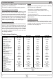
See the table below for pin assigment and levels.
Attention! Do not connect anything to pins 11 and
12.
Note: in order to remotely start or stop a charging pro-
cedure, the device has to switched to remote control by
pulling pin 7 to low. Also see the examples below.
Handling the device
Pin Name
Type
1
Description Level Electrical specifications
1 Temp sensor AO Temperature sensor LM 335 10mV/°K
2
Trickle /
Battery full
DO Charging done / Trickle charge
Charging done = High (U
High
>4V),
else = Low (U
Low
<1V)
3 Charging DO Charging active
Charging = High (U
High
>4V),
else = Low (U
Low
<1V)
4 VMON AO Actual value: voltage
0….10V corresponds to 0….100% of U
Nom
5 CMON AO Actual value: current
0….10V corresponds to 0….100% of I
Nom
6 AGND Reference for analogue signals For CMON, VMON
7 Remote DI Activate remote control
External = Low (U
Low
<1V),
Internal = High (U
High
>4V)
8 Start / Stop DI
PS mode: Power output off
Bat mode: Start/Stop charging
Off / Start = Low (U
Low
<1V),
On / Stop = High (U
High
>4V)
9 OT / OVP DO
Overtemperature OT /
Overvoltage OVP
Low = No error (U
Low
<1V)
High = Error (U
High
>4V)
Umax = 30V, Imax = 20mA
Quasi Open Collector with
pull-up to Vcc
2
10 DGND Reference for digital signals For control and monitoring signals
11 Reserved X must not be connected
12 Reserved X must not be connected
1)
AO = Analogue output, DI = digital input, DO = digital output
2)
12V...15V
U
max
= 30V, I
max
= 20mA
Quasi Open Collector with
pull-up to Vcc
2
Accuracy 0.1% at I
max
= +2mA
Short-circuit-proof against AGND
U
max
= 30V
Imax = -1mA at 5V