
User manual


57
© 2009, Elektro-Automatik GmbH & Co. KG
EN
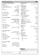
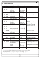
About the interface cards
Input current
if set to Low Range and Default Level = L
U
in
= 0V 0mA
U
in
= 12V +2.6mA
U
in
= 24V +5mA
if set to Low Range and Default Level = H
U
in
= 0V -1.5mA
U
in
= 12V +2.2mA
U
in
= 24V +6mA
if set to High Range and Default Level = L
U
in
= 0V 0mA
U
in
= 12V +1.6mA
U
in
= 24V +3.5mA
if set to High Range and Default Level = H
U
in
= 0V -1.5mA
U
in
= 12V +0.7mA
U
in
= 24V +4.5mA
Response time
1)
< 10ms
IF- G1 (GPIB)
Terminals 24pole Centronics socket (female)
Bus standard IEEE 488.1/2
Cable length (GPIB) 2m per device, 20m total
Cable type (GPIB) Standard GPIB cable
IF-E1 / IF-E2 (Ethernet)
Terminals 1x RJ45 (LAN / WAN)
1x USB, type A
Cable type (Ethernet) Twisted pair, patch cable,
Cat 3 or higher
Protocols VXI11, HTTP
Used ports (Ethernet) 80, 111, 200, 265
Network connection 10/100 MBit
Transmission speed Ethernet 100 kBaud
Transmission speed USB 57600 Baud
1 Time between occurance of an event, that has to be signalised to an
output, and the moment it is signalised.
3. Installation
3.1 After unpacking
After unpacking, check the pluggable interface card(s) for
signs of physical damage. If any damage can be found do
not use and insert the card into any device!
3.2 Inserting a card
The card(s) must only be inserted while the unit is completely
switched off. The unit does not have to be opened. Remove
the screws from the slot cover or from an already equipped
card and remove the cover/card. Insert the new card with
caution until the card plate touches the rear side of the unit.
If there is space between the rear side and the card pla-
te, do not tighten the screws, because the card is not
placed correctly! The wiring between the PC and/or other
units has also be done before the unit is switched on again.
The card(s) will be automatically detected by the device after
powering it on and can now be configured.
Note about the IF-A1: before equipping the card, you should
set the jumpers correctly. Refer to „4.4.1 Configuring the IF-
A1“, subsection „Digital inputs“.
Note: in case the card is not recognized after switching the
unit on, it might be necessary to update the firmware of your
device. Please contact your dealer for further information.
Caution! There are components on the card which are
sensitive for ESD. You must follow the general ESD provi-
sions when handling and installing a card.
3.3 Combining interface cards
At models with more than one card slot following restrictions
apply:
- never equip two cards of the same type
- the cards IF-R1 and IF-U1 must not be equipped together
- IF-G1 must not be combined with IF-C1 or IF-E1
- IF-E1 must not be combined with IF-C1, IF-G1, IF-R1 or
IF-U1
4. Details about the cards
The interface cards are designed to be used in various type of
device series. Depending on the typical features of a certain
device type, like for example an electronic load, the resulting
operability will change. This section handles the configuration
and handling of the cards by example of the PSI 9000 series.
But there are specific characteristics at other device series
which are explained farther below.
Information about the handling and navigation in the menus
and parameter pages of the various device types is available
the corresponding user manuals.