
User manual

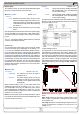


Table Of Contents
- 1. Allgemeines
- 2. Technische Daten
- 3. Installation
- 4. Details zu den Kartentypen
- 4.1 RS232-Karten IF-R1 und IF-R2
- 4.2 USB-Karten IF-U1 und IF-U2
- 4.3 CAN-Karten IF-C1 und IF-C2
- 4.4 Analoge Schnittstelle IF-A1
- 4.5 GPIB-Karte IF-G1
- 4.5.1 Hinweise zur Kommunikation
- 4.5.2 Ansteuerung des Gerätes über GPIB
- 4.5.3 Begriffserläuterung
- 4.5.4 Unterschiede zu den anderen Schnittstellenkarten
- 4.5.5 Firmware-Aktualisierungen
- 4.5.6 Ausführungs- und Übertragungszeiten
- 4.5.7 IF-G1 konfigurieren
- 4.5.8 SCPI-Befehle und Abschlußzeichen
- 4.5.9 Fehlermeldungen
- 4.6 Ethernetkarten IF-E1 und IF-E2
- 5. Einsatz in anderen Geräteserien
- 6. Der System Link Mode (nur PSI 9000)
- 7. Kommunikation mit dem Gerät
- 7.1 Begriffserklärungen
- 7.2 Vorwort
- 7.3 Allgemeine Hinweise zur Kommunikation
- 7.4 Hinweise zum USB-Treiber
- 7.5 Aufbau der Kommunikation
- 7.6 Übertragungsparameter IF-R1 und IF-U1
- 7.7 Sollwerte und Istwerte umrechnen
- 7.8 Telegrammaufbau IF-R1 und IF-U1
- 7.9 Telegrammaufbau IF-C1
- 7.10 Telegrammaufbau IF-G1
- 7.11 Telegrammaufbau IF-E1
- 8. Kommunikation mit LabView
- 9. Kommunikation ohne Labview
- 10. Anschlüsse
- 1. General
- 2. Technical specifications
- 3. Installation
- 4. Details about the cards
- 5. Operation in other device series
- 6. The System Link Mode (only PSI9000)
- 7. Communication with the device
- 7.1 Terms explained
- 7.2 Prologue
- 7.3 General notes about the communication
- 7.4 About the USB driver
- 7.5 Structure of the communication
- 7.6 Transmission settings IF-R1 and IF-U1
- 7.7 Translating set/actual values
- 7.8 Telegram structure IF-R1 and IF-U1
- 7.9 Message structure for the IF-C1
- 7.10 Message structure IF-G1
- 7.11 Message structure IF-E1
- 8. Communication with LabView
- 9. Communication without LabView
- 10. Connectors

63
© 2009, Elektro-Automatik GmbH & Co. KG
EN
About the interface cards
Examples: the input DI2/Rem-SB, which is used to switch
the power output on and off (standby), can be activated with
LOW or HIGH, depending on what has been configured in
the setup.
Example 1: the input shall be pulled to GND by a relay (maker
contact) and switch the power output off. Hence you need
to configure the jumper for DI2 to „Default level = H“ and
use the settings Standby = LOW and Set output = enable
ON. The output of the power supply can then be switched
by the relay.
Example 2: the output shall be shut off by an emergency
circuit. The jumper for DI2 needs to be set to „Default level
=L“ and the setting Standby = LOW. This example uses a
relay with a maker contact to Vcc.
There are, of course, many other possible combinations.
Digital outputs with determined functionality
The digital outputs DO1, DO4, DO5 and DO6 can not be
user-defined in their functionality, but they can invert the
logical output level.
DO1/CV Default: LOW
= { LOW | HIGH }
If LOW has been selected, the output is pulled to GND as
soon as the regulation mode of the power supply is determi-
ned by the set value of voltage (CV operation). If HIGH has
been selected, the output is pulled to 12...15V.
DO4/Mains OK Default: LOW
= { LOW | HIGH }
If LOW has been selected, the output is pulled to GND as long
as the mains voltage is present. If HIGH has been selected,
the output is pulled to 12...15V.
DO5/Standby Default: LOW
= { LOW | HIGH }
If LOW has been selected, the output is pulled to GND if the
power output of the device is off (standby). If HIGH has been
selected, the output is pulled to 12...15V.
DO6/CC Default: LOW
= { LOW | HIGH }
If LOW has been selected, the output is pulled to GND as
soons as the regulation mode of the power supply is deter-
mined by the set value of current (CC operation). If HIGH
has been selected, the output is pulled to 12...15V.
Digitaloutputswithuser-denablefunctionality
ThedigitaloutputDO2,DO3andDO7canbeconguredas
desired and the logical level can be inverted.
DO2 Default: OVP LOW
DO3 Default: OT LOW
DO7 Default: CP LOW
One of the following functions can be assigned to each of
the outputs:
= remote Indicates that the power supply is remotely-
controlled via a digital interface card.
= OT Indicates an overtemperature error.
= CP Indicates that the power supply regulated by
the set value of power (CP operation).
= Alarm Indicates that an alarm has happened. The
output of the power supply is automatically
shut down and the alarm can be indicated by
this output.
= trip U Triggered by overstepping of the limits U>
and/or U< (see user‘s guide of PSI9000).
= trip I Triggered by overstepping of the limits I>
and/or I< (see user‘s guide of PSI9000).
= trip U+I Triggered by overstepping of the limits U>, U<,
I> and/or I< (see user‘s guide of PSI9000).
Deningthelogicallevelwhentriggered/indicated:
= LOW The output is pulled against GND as soon as
the selected function becomes active. The
logical level is inverted, if the condition is not
true.
= HIGH The output is pulled against +15V by a high
resistance resistor as soon as the selected
function is active. The logical level is inverted,
if the condition is not true.