Elektronische Lasten Serie Electronic Load Series EL 9000 HP 80V/160V/400V/750V 50A/100A/200A/400A 4800W EL 9080-400 HP: 33 200 241 EL 9160-200 HP: 33 200 243 EL 9400-100 HP: 33 200 245 EL 9750-50 HP: 33 200 250
DE Allgemeines Impressum Elektro-Automatik GmbH & Co. KG Helmholtzstrasse 31-33 41747 Viersen Germany Telefon: 02162 / 37850 Fax: 02162 / 16230 Web: www.elektroautomatik.de Mail: ea1974@elektroautomatik.de © Elektro-Automatik Nachdruck, Vervielfältigung oder auszugsweise, zweckentfremdete Verwendung dieser Bedienungsanleitung sind verboten und können bei Nichtbeachtung rechtliche Schritte nach sich ziehen.
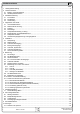
Inhaltsverzeichnis DE Seite 1. Leistungsbeschreibung......................................................................................................................................... 5 2. Technische Daten.................................................................................................................................................. 5 2.1 Bedien- und Anzeigeeinheit........................................................................................................................
DE Über das Gerät 1. Leistungsbeschreibung Die elektronischen Lasten der Serie EL 9000 HP sind sehr leistungsfähige Geräte, die in einem 19“ Gehäuse und 6HE eine Vielzahl von interessanten Möglichkeiten bieten. Über die gängigen Funktionen von elektronischen Lasten hinaus können Batterien getestet werden und Spannungs- oder Stromquellen mit einem Pulsbetrieb belastet werden, bei dem die Pulsdauer und die Amplitude einstellbar sind.
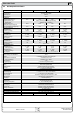
DE Über das Gerät 2.2 Gerätespezifische Daten EL9080-400 HP EL 9160-200 HP Netzeingang Netzspannung Netzfrequenz Netzsicherung EL9400-100 HP EL9750-50 HP 115V/230V umschaltbar 50/60Hz T2,5A DC-Eingang Eingangsspannung Unenn Eingangsleistung Pnenn 80V - Dauerleistung Eingangsstrom Inenn 400A Überspannungsschutzgrenze maximal zulässige Eingangsspg.
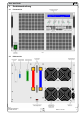
DE Über das Gerät 3. Gerätebeschreibung 3.1 Frontansicht Bild 1 3.2 Rückansicht Bild 2 Bedienungsanleitung EL 9000 HP Serie Stand: 31.10.
DE Über das Gerät 3.3 Lieferumfang 1 x Elektronische Last 1 x gedruckte Bedienungsanleitung 1 x Netzkabel 1 x WAGO-Stecker 7polig (System Bus, gesteckt) 4. Allgemeines zum Gerät 4.1 Vorwort/Warnhinweis Diese Bedienungsanleitung und das zugehörige Gerät sind für Anwender gedacht, die sich mit dem Prinzip einer elektronischen Last und deren Anwendung auskennen.
DE Über das Gerät 4.7 Verhalten Eingangsspannung zu Eingangsstrom Für Anwendungen mit relativ geringer Eingangsspannung ist es interessant zu wissen, bei welcher minimalen Eingangsspannung die Last den maximalen Strom aufnimmt. Technisch bedingt ist diese minimale Eingangsspannung nicht 0 und variiert von Modell zu Modell, maßgeblich durch die Anzahl der verwendeten Transistoren bestimmt.
DE Über das Gerät 6. Bedienung Alarmmanagement Für eine Übersicht aller Bedien- und Anzeigeelemente siehe auch Abschnitt 3.1. Die Meldungen Overvoltage (Überspannung) und Power fail (Eingangsspannungsfehler) zeigen Gerätefehler an. 6.1 Die Anzeige Ein Eingangsspannungsfehler tritt auf, wenn die Netzspannung zu niedrig ist und ein Überspannungsfehler wird bei zu hoher DC-Eingangsspannung auftreten. Dies ist eine Übersicht über die zweizeilige Anzeige und deren Aufteilung.
DE Bedienung des Gerätes 6.2 Die Bedienelemente Netzschalter Power (1) Dient zum Ein- und Ausschalten des Gerätes. Bedeutung der einzelnen Schalterstellungen: A Schaltet auf die Sollwerte für den Level A um. Diese werden nach dem Umschalten sofort gesetzt. B Schaltet auf die Sollwerte für den Level B um. Diese werden nach dem Umschalten sofort gesetzt. A/B Schaltet die Last offline und aktiviert den Pulsbetrieb (frequenzbehafteter, automatischer Wechsel zwischen Level A und B).
DE Bedienung des Gerätes In der Betriebsart Level A/B oder im Einstellungs-Menü sind mehrere „Seiten“ anwählbar. Dort erscheinen am rechten Rand der Anzeige zwei auf und ab zeigende Dreiecke, die symbolisieren sollen, daß hier noch weitergeschaltet werden kann. Wenn man durch Links- oder Rechtsdrehung am Ende angekommen ist, springt der Pfeil wieder zurück auf die erste bzw. letzte Einstellseite. Drehknopf Setting (6) Dieser Drehknopf hat keinen Endanschlag.
DE Bedienung des Gerätes Ein Wechsel der Regelungsart auf CC setzt den zuletzt einstellten Sollwert für Leistung auf Maximum und den Sollwert für den Strom auf 0, wenn in den Einstellungen der Parameter Keep set values auf no gestellt wurde. Bei Auswahl yes werden die zuletzt eingestellten Sollwerte weiter benutzt. Siehe auch „7.1. Das Einstellungs-Menü“. CV bedeutet Konstantspannungsbetrieb. Hierbei sind die Werte für Spannung, Strom und Leistung veränderbar.
DE Bedienung des Gerätes 6.7.1 Level A Bei Auswahl der Betriebsart Level A mit dem Schalter Level Control (3) werden die Sollwerte von Level A aktiv. Dies ist allerdings nur möglich, wenn die Last nicht im Remote mode oder im External mode ist. In der Anzeige wird Level A angezeigt und ein Pfeil (->) vor den zur gewählten Regelungsart gehörenden Sollwert gesetzt, damit dieser sofort variiert werden kann.
DE Bedienung des Gerätes Mit dem Drehknopf Selection(5) können die Sollwerte für A und B, sowie die beiden Pulszeiten für Level A und B angewählt und eingestellt werden. In der Anzeige erscheinen zur Kennzeichnung der Zugehörigkeit A und B. Bei der Auswahl des einzustellenden Wertes wird wiederum ein Pfeil (->) vor den Wert gestellt. Zusätzlich ist noch die Anstiegs-/Abfallzeit für den automatischen Wechsel zwischen A nach B einstellbar.
DE Bedienung des Gerätes 6.9 Bedienung Vor und während des Tests können der Sollwert der vorgewählten Regelungsart (CC, CR oder CP) und die Unterspannungsabschaltschwelle Ulow justiert werden. Die Auswahl des einzustellenden Wertes erfolgt mit Selection(5) und Justierung mit Setting(6). In der Anzeige werden außerdem die beim Test ablaufende Zeit im Format Stunden:Minuten:Sekunden (HH:MM:SS), sowie die entnommene Kapazität in Ah angezeigt.
DE Bedienung des Gerätes 6.10 Reihen- und Parallelschaltung Eine Parallelschaltung von mehreren Lasten ist möglich, wird aber von diesen Modellen nicht explizit unterstützt. Das heißt, es findet keine automatische Verteilung des Stromes bei Parallelschaltung statt. Der Anwender muß selbst dafür sorgen, daß die Geräte dabei richtig bedient bzw. angesteuert werden.
DE Bedienung des Gerätes 7. Gerätekonfiguration 7.1 Das Einstellungs-Menü Das Einstellungs-Menü kann nur mit dem Schalter Level Control(3) auf Stellung Setup aktiviert werden, außer bei Fernsteuerbetrieb. Solange die Last in der Betriebsart Setup ist, ist kein normaler Lastbetrieb möglich. In der Anzeige werden für den Betrieb benötigte Parameter angezeigt, die mit Selection(5) ausgewählt und mit Setting(6) verändert werden können.
DE Bedienung des Gerätes CAN Base ID (ab Firmware 5.01) Wertebereich: 0x000 (0000) ... 0x7FC (2044) Standardwert: 0x000 (0000) Zugehörigkeit: CAN-Schnittstellenkarte IF-C1 Bedeutung: stellt die Basis-ID für das CAN-ID-System mit drei IDs ein, wie sie für die Einstellung Vector verwendet werden (siehe oben CAN ID System). Dieses ID-System ist kompatibel zu Software der Firma Vector und kann mit sogenannten Datenbasen (*.dbc) verwendet werden. Einstellbar in 4er-Schritten.
DE Bedienung des Gerätes 8. Die Analogschnittstelle Erläuterung Die analoge Schnittstelle, nachfolgend auch AS genannt, ist eine 15polige Sub-D-Buchse und befindet sich auf der Rückseite. Sie ist so konzipiert, daß man damit die wichtigsten Funktionen der elektronischen Last über externe Hardware (Spannungsgeber, SPS, Schalter, Relais usw.) fernsteuern kann. Die Last muß für die Benutzung der analogen Schnittstelle umgeschaltet werden.
DE Bedienung des Gerätes 8.3 Anwendungen Übersicht der Pins AGnd DGnd Remote Rem-SB RSEL PSEL CSEL VSEL REM-SB REMOTE DGND Bild 18 OVP/OT Trigger In R-Range R-active VMON CMON VRef Bild 16 Master-Slave-Betrieb, Nachbildung Echter Master-Slave-Betrieb ist hier nicht möglich, da die AS keine Sollwerte herausgibt. Man kann jedoch die Istwertausgänge CMON und in einigen Fällen auch VMON benutzen, um mindestens einen von den vier Sollwerteingängen anderer Lasten anzusteuern.
DE Bedienung des Gerätes Fernsteuerung nur mit Stromregelung Wie im Beispiel oben, hier mit nur Strom regelbar. Die Leistung ist fest auf Maximum. DGND VREF CSEL AGND 10k Bild 21 8.4 Pinbelegung Analogschnittstelle Pin Name Typ² Bezeichnung Pegel 1 VSEL AI Sollwert Spannung 0…10V, entspricht 0..100% von U Nenn Genauigkeit typ. 0,1% 2 CSEL AI Sollwert Strom 0…10V, entspricht 0..100% von I Eingangsimpedanz Ri > 40k…100K 3 PSEL AI Sollwert Leistung 0…10V, entspricht 0..
DE Bedienung des Gerätes 9. Schnittstellenkarten Allgemeines Die elektronische Last unterstützt verschiedene Schnittstellenkarten. Die digitalen Schnittstellenkarten IF-R1(RS232), IFC1(CAN) und IF-U1(USB) unterstützen ein binäres Kommunikationsprotokoll. Die IEEE-Karte IF-G1 hat ein textbasiertes Kommunikationsprotokoll nach SCPIStandard.
Bedienung des Gerätes DE 10. Sonstiges 10.1 Zubehör und Optionen Hinweis: Detaillierte Informationen über Optionen und Zubehör sind in separaten Handbüchern bzw. auf Anfrage erhältlich. Folgendes Zubehör ist optional erhältlich: a) USB-zu-Analog-Interface UTA12 Galvanisch getrennte Fernsteuerung über USB (PCSeite) und die im Gerät integrierte Analogschnittstelle.
EN General About Elektro-Automatik GmbH & Co. KG Helmholtzstrasse 31-33 41747 Viersen Germany Phone: +49 2162 / 37850 Fax: +49 2162 / 16230 Web: www.elektroautomatik.de Mail: ea1974@elektroautomatik.de © Elektro-Automatik Reprint, duplication or partly, wrong use of this instruction manual are prohibited and might be followed by legal consequences.
Table of contents EN Page 1. Introduction.......................................................................................................................................................... 27 2. Technical specifications....................................................................................................................................... 27 2.1 Control panel................................................................................................................................
EN About the device 1. Introduction The electronic loads of the series EL 9000 HP are very efficient devices which offer a big variety of interesting features in a 19“ case of 6U. Besides the common functionality of electronic loads you can test batteries, load voltage or current sources with a pulsed operation, where the pulse widths and the amplitude are adjustable. Or you can remotely control the device via an interface card and control and monitor nearly all its features from a PC.
EN About the device 2.2 Device specific data EL9080-400 EL 9160-200 Mains input Mains voltage Mains frequency Mains fuse EL9400-100 EL9400-100 S01 EL9750-50 115V/230V selectable 50/60Hz T2,5A DC input Input voltage Unom Input power Pnom 80V - permanent power Input current Inom 400A Overvoltage protection threshold max. allowed input voltage 160V 400V 460V 4800W, with temperature related derating 3000W at 20°C ambient temp. 200A 100A 100A 1.
EN About the device 3. Design 3.1 Front view Figure 1 3.
EN About the device 3.3 Scope of delivery 1 x Electronic load 1 x Printed instruction manual 1 x Mains cord 1 x WAGO plug 7pole (System Bus, plugged) The instability is not caused by a malfunction of the load, but by the behaviour of the complete system. An improvement of the phase and gain margin can solve this. In practice, a capacity is directly connected to the DC input of the load. Recommended is 1µF, for slower systems some 100µF can be necessary. 4.6 4. General 4.
EN About the device 4.7 Relation of input voltage to input current When working with applications that input only low voltages to the load, it becomes necessary to know the minimum input voltage that is required for the load to draw the full input current. That minimum voltage is not zero and, depending on the number of transistors inside, it varies from model to model.
EN Handling the device 6. Handling 6.1 The display For an overview of all operating elements also see section 3.1. This is an overview of the two line display and its layout. The left side always shows actual values while the load input is switched on: Figure 3 The indicator for the regulation mode(a triangle) appears next to the actual value, which is related to currently active regulation mode of the load. This can differ from the chosen regulation mode if a nominal value has been exceeded.
EN Handling the device 6.2 Operating elements Mains switch Power (1) Is used to switch the device on or off. Selector Mode (2) Is used to preselect the regulation mode in which the device shall work. The different regulation modes effect each other. As soon as actual values reach set values, the regulation mode changes. This can, for example, lead to a dominance of the constant power control (CP), even if the constant current control (CC) is set as active mode.
EN Handling the device Rotary knob Setting (6) This rotary knob has no end stop. With every position Setting (6) changes the set value resp. the parameter (in the setup menu) which was chosen before by Selection (5). It applies: the faster the knob is rotated, the faster the set value is increased or decreased (the step width changes). Slow rotation hence changes the set value in small steps, while fast rotation changes it in big steps.
EN Handling the device A changeover to regulation mode CV can reset the set values of voltage, power and current to their nominal values, if the parameter Keep set values has been set to no in the setup. If set to yes, the least adjusted set values are kept. Also see „7.1. The setup menu“. A changeover to regulation mode CR can reset the set values of resistance, current and power to their nominal values, if the parameter Keep set values has been set to no in the setup.
EN Handling the device 6.7.2 Level B When switching to „Level B“ with the selector Level Control(3), the set values of Level B become active. This mode works the same way as Level A. The adjusted rise/fall time is still effective here, but the pulse widths are now determined by the trigger signal, which is fed into the trigger input. The trigger signal must be square wave, for levels see „8. The analogue interface“.
EN Handling the device 6.8 The battery test mode Introduction Figure 12 Figure 12 shows a possible progression of a set value (U, I, P or R) with adjustable pulse widths and variable amplitude. The rise/fall time is also adjustable, but is equal for A and B. If the rise/fall time is set to minimum, the signal of the pulsed operation is a nearly ideal square wave. Figure 12 is only a clarifying view.
EN Handling the device Figure 13. Battery test operation in current control (CC) mode 6.9 Control locations and priorities Control locations are the locations from where the device is controlled. This can be at the device (manual control), via the analogue interface (external control) or via a digital interface card (remote control). In order to prevent the user from accessing the device from two locations at once there are priorities.
EN Handling the device 6.11.2 Selecting the regulation speed The regulation speed (or time) of the load has deliberately been set to slow and lies at typical 50ms (only for CV and CP mode). By this setting it is accomplished that critical feeding sources like power supplies with unknown regulation characteristics can be loaded steadily and run free from unwanted oscillation. The dynamics is then situated at the given minimal regulation time. See „2. Technical specifications“, section „Dynamics“.
EN Settings 7. Device configuration 7.1 The setup menu The setup menu can only be activated by the selector Level(3), except during remote control. While the load is in setup, no normal load operation is possible. The display shows a certain number of parameters, depending on which interface card is installed. The parameters are selected by knob Selection(5) and changed with knob Setting(6). Two small triangles on the right side of the display indicate that multiple parameters are available.
EN Settings CAN Base ID (available since firmware 5.01) Possible settings: 0x000 (0000) ... 0x7FC (2044) Default setting: 0x000 (0000) Belongs to: CAN interface card IF-C1 Explanation: this adjusts the base ID for the CAN ID system which uses three IDs (see above at CAN ID System). With the three IDs per unit, the system is compatible to Vector software and the so-called CAN databases (*.dbc). The base ID is adjustable in steps of four.
EN Remote control 8. The analogue interface Introduction The analogue interface is a 15pole Sub-D socket and is located at the rear side. It is designed to remotely control the most important functions of the electronic load by external hardware (eg. SPS, switches, relays) with it. The load requires to be switched to external control in order to use the analogue interface. This is done by connecting Pin 7 (Remote) with ground (Pin 6) by a jumper or switch.
EN Remote control 8.3 Example applications Overview of the pins AGnd DGnd Remote Rem-SB RSEL PSEL CSEL VSEL REM-SB REMOTE DGND Figure 18 OVP/OT Trigger In R-Range R-active VMON CMON VRef Figure 16 Master-Slave operation, simulated A true Master-Slave is not possible because the analogue interface does not provide set value outputs.
EN Remote control External control with current only Like in the example above, but only current adjustable. The power is set to maximum. DGND VREF CSEL AGND 10k Figure 21 8.4 Pin assignment of the analogue interface Pin Name Type² Description Level Electrical specifications 1 VSEL AI Set value for voltage 0…10V, corresponds to 0..100% of U Nom Accuracy typically 0.1% 2 CSEL AI Set value for current 0…10V, corresponds to 0..
EN Remote control 9. Interface cards General The electronic load supports various interface cards. The digital interface cards IF-R1(RS232), IF-C1(CAN) and IF-U1(USB) support a uniform communication protocol. The IEEE/GPIB card IF-G1 uses a text based protocol according to the SCPI standard. All cards can be used to monitor and control 1 to 30 units by a PC, whereas the total number of devices using IEEE is limited to 15 by the bus standard.
EN Other 10. Miscellaneous 10.1 Accessories and options Note: Details about options and accessories are avaible in seperate instruction manuals. Following accessories are optionally available: a) USB-to-Analogue interface UTA12 Galvanically isolated remote control via USB (on PC side) and the device internal analogue interface.
EA-Elektro-Automatik GmbH & Co. KG Entwicklung - Produktion - Vertrieb Helmholtzstraße 31-33 41747 Viersen Germany Telefon: 02162 / 37 85-0 Telefax: 02162 / 16 230 ea1974@elektroautomatik.de www.elektroautomatik.